
Town & Country V6-3.8L VIN L (2006)
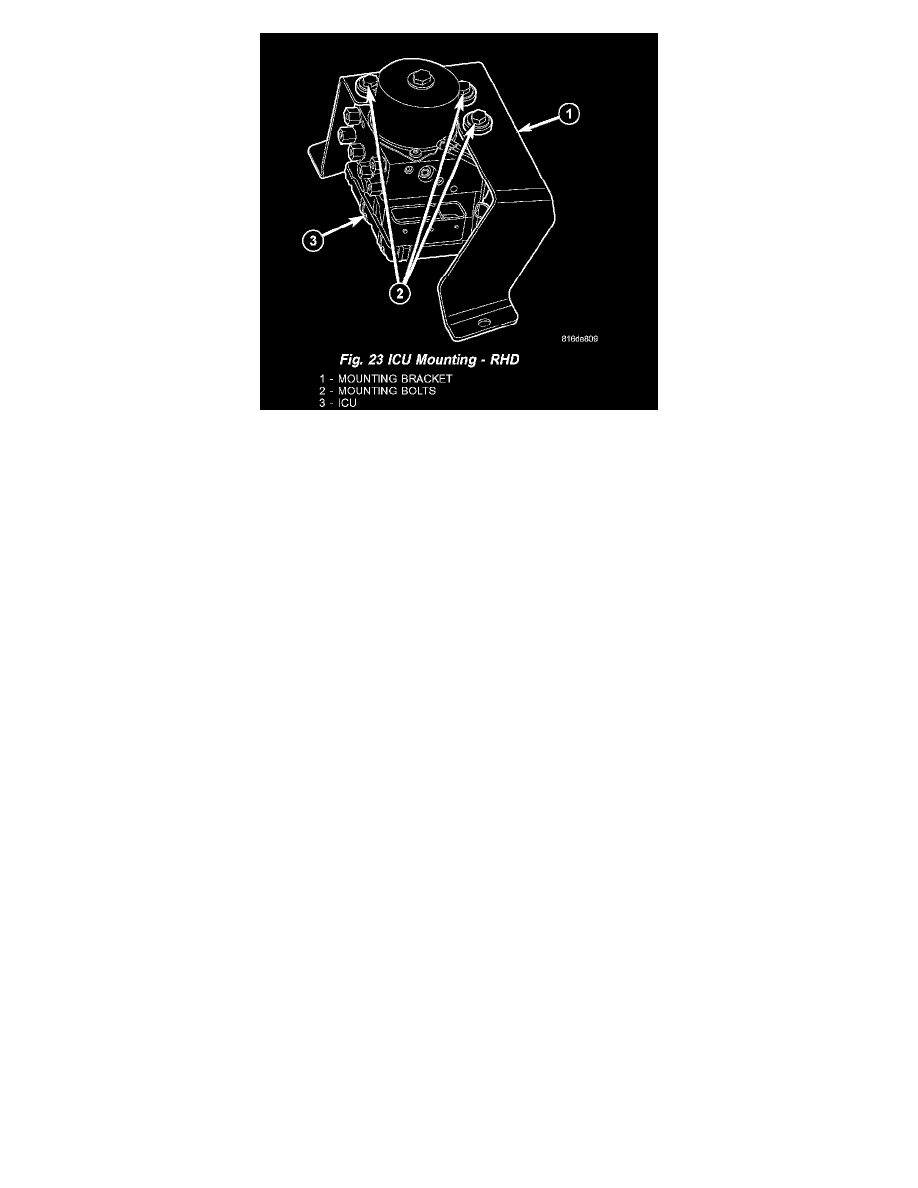
Fig. 23 ICU Mounting - RHD
11. Remove the 3 bolts mounting the ICU to the upper mounting bracket (Fig. 23). Separate the ICU from the mounting bracket.
12. Separate the CAB and HCU if needed.
INSTALLATION
1. Install the ICU on the mounting bracket (Fig. 23). Install and tighten the three mounting bolts to 11 Nm (97 inch lbs.).
2. Install the ICU and its mounting brackets as an assembly on the front suspension crossmember. Install the Three bolts attaching the ICU brackets
to the crossmember (Fig. 22). Tighten the mounting bolts to 24 Nm (18 ft. lbs.).
3. Install the power steering cooler to the ICU mounting bracket (Fig. 21). Install and tighten the mounting screws to 10 Nm (90 inch lbs.).
4. Clip the front brake tubes in the routing clip on the ICU mounting bracket (Fig. 20).
CAUTION: When installing the chassis brake tubes on the HCU valve block, they must be located correctly in the valve block to ensure proper
ABS operation.
5. Install all six brake tubes into their correct port locations on the HCU valve block as shown (Fig. 20). Tighten the tube nuts to 17 Nm (145 inch
lbs.).
NOTE: Before connecting the wiring harness connector to the CAB, be sure the seal is properly installed in the connector.
6. Connect the wiring harness connector to the CAB as follows: Position the connector in the socket of the CAB and carefully push it down as far as
possible. When connector is fully seated by hand, push in the connector lock. This will pull the connector into the socket and lock it in the installed
position.
7. Lower the vehicle.
8. Remove the brake pedal holder.
9. Connect the negative cable back to the negative post of the battery.
10. Hook up a scan tool to initialize the CAB and check for any faults.
11. Fill the master cylinder with clean, fresh Mopar Brake Fluid or equivalent, then bleed base brakes and ABS.
12. Road test the vehicle to ensure proper operation of the base and antilock brake systems.
MK25E
INTEGRATED CONTROL UNIT (ICU) - MK25E
REMOVAL
1. Disconnect the negative (ground) cable from the battery and isolate it.
2. Remove the battery shield and battery.
3. Disconnect the vacuum hose connector at the tank built into the battery tray.
4. Remove the screw securing the engine coolant filler neck to the battery tray.
5. Remove the battery tray.
6. Using a brake pedal depressor, move and lock the brake pedal to a position past the first inch of pedal travel. This will prevent brake fluid from
draining out of the master cylinder once the brake tubes are removed from the ICU.
7. Disconnect the wiring harness connector from the speed control servo.