
Town & Country V6-3.8L VIN L (2006)
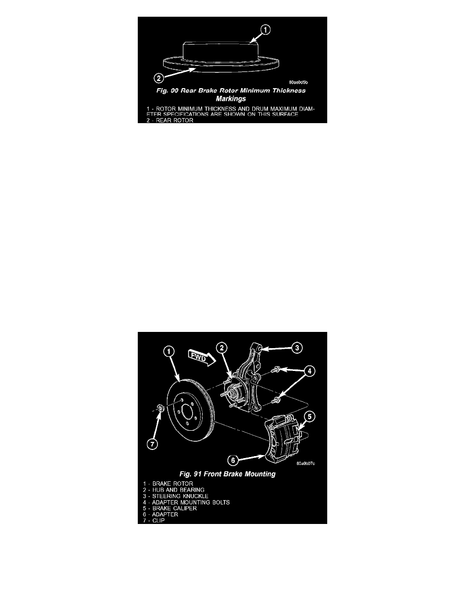
Fig. 90 Rear Brake Rotor Minimum Thickness Markings
NOTE: All rotors have markings for minimum allowable thickness cast on an un-machined surface of the rotor (Fig. 89) (Fig. 90). Minimum
thickness specifications can also be found in the specification table.
Minimum allowable thickness is the minimum thickness which the brake rotor machined surface may be cut to.
CAUTION: Do not machine the rotor if it will cause the rotor to fall below minimum thickness.
Before installation, verify the brake rotor face and the hub adapters are free of any chips, rust, or contamination.
When mounting and using the brake lathe, strict attention to the brake lathe manufacturer's operating instructions is required.
Machine both sides of the brake rotor at the same time. Cutting both sides at the same time minimizes the possibility of a tapered or uneven cut.
When refacing a rotor, the required TIR (Total Indicator Reading) and thickness variation limits MUST BE MAINTAINED. Extreme care in the
operation of rotor turning equipment is required. Specifications for brake rotor machining can be found in specification table.
Removal and Installation
REMOVAL - FRONT BRAKE ROTOR
1. Raise vehicle on jackstands or centered on a frame contact type hoist.
2. Remove the front wheel and tire assembly.
Fig. 91 Front Brake Mounting
3. Remove the two mounting bolts securing the disc brake caliper adapter with brake caliper to the steering knuckle (Fig. 91).
4. Remove the disc brake caliper and adapter as an assembly from the steering knuckle (Fig. 91). Hang the assembly out of the way using wire or a