
Town & Country V6-4.0L (2008)
11. Remove the clockspring from the steering column.
12. Unlatch and remove the multi-function switch and, if the vehicle is so equipped, the adjustable pedal switch from the clockspring mounting
bracket.
13. The clockspring and the SAS cannot be repaired. They must be replaced as a unit if either is ineffective or damaged, or if the driver airbag has
been deployed.
Installation
INSTALLATION
WARNING: To avoid serious or fatal injury on vehicles equipped with airbags, disable the Supplemental Restraint System (SRS) before
attempting any steering wheel, steering column, airbag, seat belt tensioner, impact sensor, or instrument panel component diagnosis or service.
Disconnect and isolate the battery negative (ground) cable, then wait two minutes for the system capacitor to discharge before performing
further diagnosis or service. This is the only sure way to disable the SRS. Failure to take the proper precautions could result in accidental
airbag deployment.
CAUTION: If the clockspring is not properly centered in relation to the steering wheel, steering shaft and steering gear, the clockspring tapes
WILL be damaged, and such damage is NOT covered under the provisions of the vehicle warranty. If clockspring centering is not maintained
during the performance of any vehicle service procedure, the clockspring centering procedure MUST be performed. See: Procedures. Service
replacement clocksprings are shipped pre-centered and with a locking pin installed. This locking pin should not be removed until after the
steering wheel has been installed on the steering column. If the locking pin is removed before the steering wheel is installed on a steering
column, the clockspring centering procedure MUST be performed.
NOTE: Before starting this procedure, be certain that the front wheels are still in the straight-ahead position.
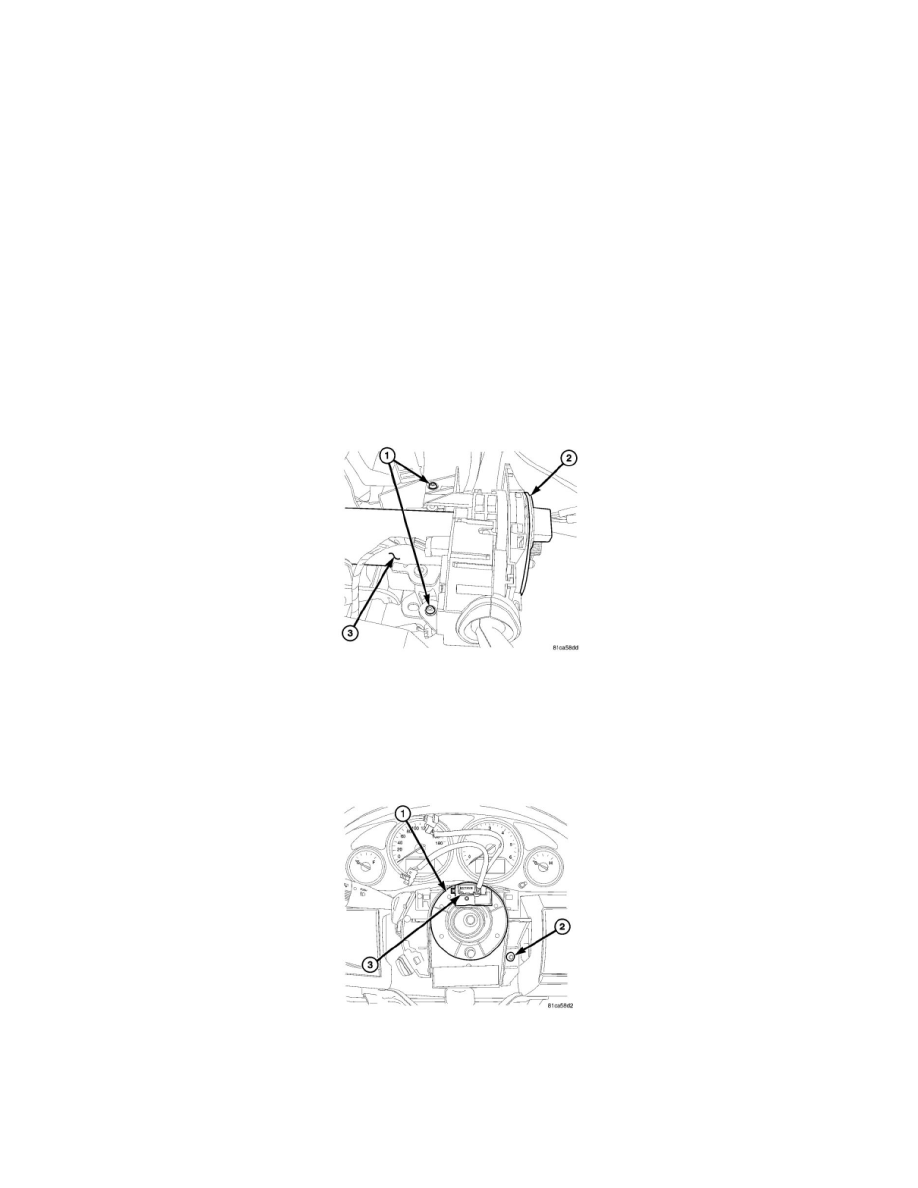
1. Engage and latch the multi-function switch and, if the vehicle is so equipped, the adjustable pedal switch onto the clockspring (2) mounting
bracket.
2. Carefully slide the centered clockspring down over the steering column (3) upper shaft.
3. Reconnect the instrument panel wire harness connectors to the connector receptacles on the backs of the multi-function switch, the adjustable
pedal switch (if equipped), the Steering Angle Sensor (SAS) and the clockspring.
4. From above the steering column, align and fully tighten the two captive upper screws (1) that secure the back of the clockspring to the column.
Tighten the screws securely.
5. Install and tighten the lower screw (2) that secures the face of the clockspring (1) to the steering column.
6. Reinstall the shrouds onto the steering column.See: Steering and Suspension/Steering/Steering Column/Steering Column Cover/Service and
Repair/Shroud - Lower/Installation.
NOTE: When reinstalling the steering wheel, be certain to index the engagement dowel/drive pin on the upper surface of the clockspring
rotor with the slot cast into the lower surface of the steering wheel armature hub.