
Town & Country AWD V6-3.8L VIN L (2003)
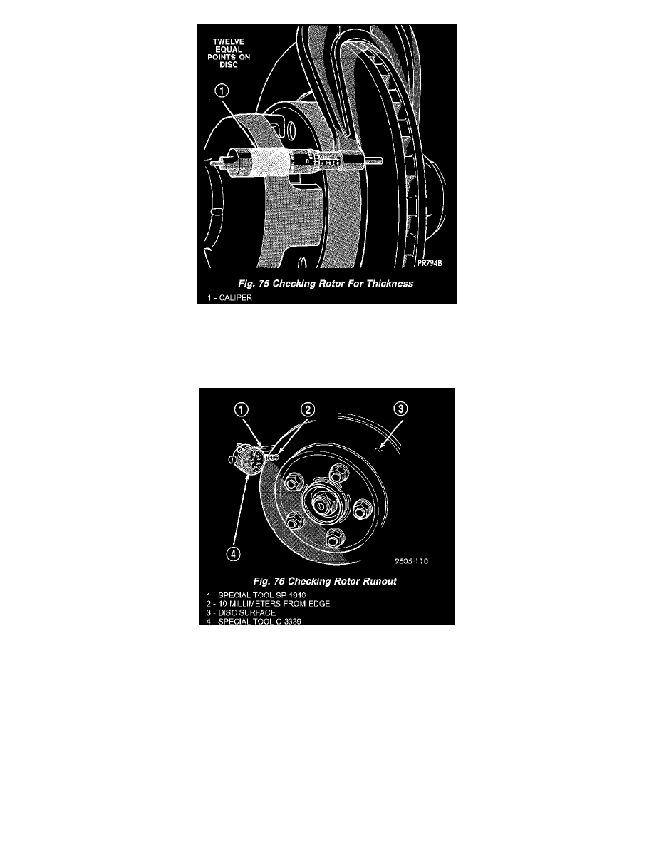
Rotor thickness variation measurements should be made in conjunction with measuring runout. Measure thickness of the brake rotor at 12 equal points
around the rotor braking surface with a micrometer at a radius approximately 25 mm (1 inch) from edge of rotor. If thickness measurements vary
beyond the specification, the rotor should be refaced or replaced.
ROTOR RUNOUT
On-vehicle rotor runout is the combination of the individual runout of the hub face and the runout of the rotor. (The hub and rotor runouts are
separable). To measure rotor runout on the vehicle, first remove the tire and wheel assembly. Reinstall the wheel mounting nuts on the studs,
tightening the rotor to the hub. Mount the Dial Indicator, Special Tool C-3339, with Mounting Adaptor, Special Tool SP1910 on steering arm. The
dial indicator plunger should contact braking surface of rotor approximately ten millimeters from edge of rotor. Check lateral runout on both sides of
the rotor, marking the low and high spots on both. Runout limits can be found in specifications.