
Town & Country AWD V6-3.8L VIN L (2003)
Differential Carrier: Description and Operation
DIFFERENTIAL ASSEMBLY
DESCRIPTION
The differential gear system divides the torque between the axle shafts. It allows the axle shafts to rotate at different speeds when turning corners.
Each differential side gear is splined to an axle shaft. The pinion gears are mounted on a pinion mate shaft and are free to rotate on the shaft. The pinion
gear is fitted in a bore in the differential case and is positioned at a right angle to the axle shafts.
OPERATION
In operation, power flow occurs as follows:
-
The pinion gear rotates the ring gear
-
The ring gear (bolted to the differential case) rotates the case
-
The differential pinion gears (mounted on the pinion mate shaft in the case) rotate the side gears
-
The side gears (splined to the axle shafts) rotate the shafts
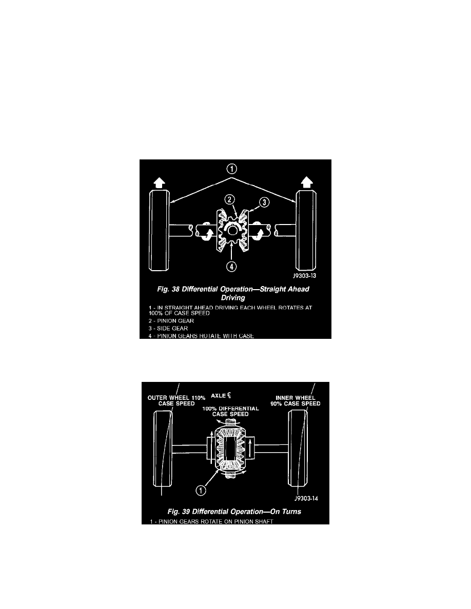
During straight-ahead driving, the differential pinion gears do not rotate on the pinion mate shaft. This occurs because input torque applied to the gears is
divided and distributed equally between the two side gears. As a result, the pinion gears revolve with the pinion mate shaft but do not rotate around it
(Fig. 38).
When turning corners, the outside wheel must travel a greater distance than the inside wheel to complete a turn. The difference must be compensated for
to prevent the tires from scuffing and skidding through turns. To accomplish this, the differential allows the axle shafts to turn at unequal speeds (Fig.
39). In this instance, the input torque applied to the pinion gears is not divided equally. The pinion gears now rotate around the pinion mate shaft in
opposite directions. This allows the side gear and axle shaft attached to the outside wheel to rotate at a faster speed.