
Town & Country LWB FWD V6-3.8L VIN L (1999)
Hydraulic Control Assembly - Antilock Brakes: Description and Operation
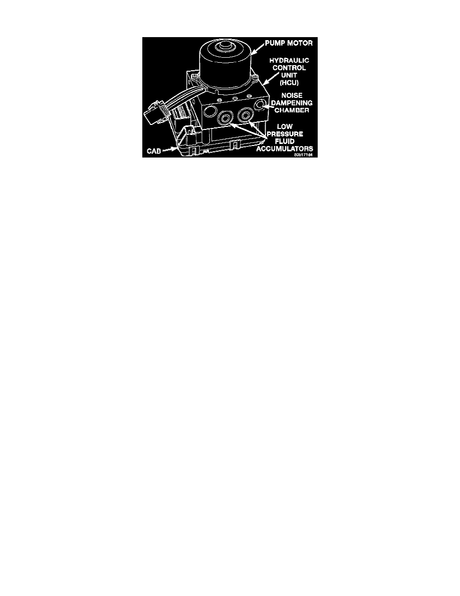
Teves Mark 20 ICU
The Hydraulic Control Unit (HCU) is mounted to the CAB as part of the ICU. The ICU is located on the driver's side of the front suspension cradle
under the vehicle. The HCU controls the flow of brake fluid to the brakes using a series of valves and accumulators. A pump/motor is mounted on the
HCU to supply build pressure to the brakes during an ABS stop.
The HCU on a vehicle equipped with ABS and traction control has a valve block housing that is approximately 1 inch longer on the low pressure fluid
accumulators side than a HCU on a vehicle that is equipped with only ABS.
VALVES AND SOLENOIDS
The valve block contains four inlet valves and four outlet valves. The inlet valves are spring-loaded in the open position and the outlet valves are
spring loaded in the closed position during normal braking. The fluid is allowed to flow from the master cylinder to the wheel brakes.
During an ABS stop, these valves cycle to maintain the proper slip ratio for each wheel. The inlet valve closes preventing further pressure increase and
the outlet valve opens to provide a path from the wheel brake to the HCU accumulators and pump/motor. This releases (decays) pressure from the
wheel brake, thus releasing the wheel from excessive slippage. Once the wheel is no longer slipping, the outlet valve is closed and the inlet valve is
opened to reapply (build) pressure.
On vehicles with traction control, there is an extra set of valves and solenoids. The ASR valves, mounted in the HCU valve block, are normally in the
open position and close only when the traction control is applied.
These isolator valves are used to isolate the rear (non-driving) wheels of the vehicle from the hydraulic pressure that the HCU pump/motor is sending
to the front (driving) wheels when traction control is being applied. The rear brakes need to be isolated from the master cylinder when traction control
is being applied so the rear wheels do not drag. For more information, see Traction Control System.
BRAKE FLUID ACCUMULATORS
There are two fluid accumulators in the HCU-one for the primary hydraulic circuit and one for the secondary hydraulic circuit. Each hydraulic circuit
uses a 5 cc accumulator.
The fluid accumulators temporarily store brake fluid that is removed from the wheel brakes during an ABS cycle. This stored fluid is used by the
pump/motor to provide build pressure for the brake hydraulic system. When the antilock stop is complete, the accumulators are drained by the
pump/motor.
On ABS-only vehicles, there is a mini-accumulator on the secondary hydraulic circuit that protects the master cylinder seals during an ABS stop, and
there is a noise dampening chamber on the primary circuit.
On ABS with traction control vehicles, there are two noise dampening chambers in the HCU.
PUMP/MOTOR
There are two pump assemblies in the HCU-one for the primary hydraulic circuit and one for the secondary hydraulic circuit. Both pumps are driven
by a common electric motor. This DC-type motor is integral to the HCU and is controlled by the CAB.
The pump/motor provides the extra amount of brake fluid needed during antilock braking. Brake fluid is released to the accumulators when the outlet
valve is opened during an antilock stop. The pump mechanism consists of two opposing pistons operated by an eccentric camshaft. In operation, one
piston draws fluid from the accumulators, and the opposing piston pumps fluid to the master cylinder circuits. When the antilock stop is complete, the
pump/motor drains the accumulators.
The CAB may turn on the pump/motor when an antilock stop is detected. The pump/motor continues to run during the antilock stop and is turned off