
Town & Country Van V6-201 3.3L VIN R SMFI (1990)
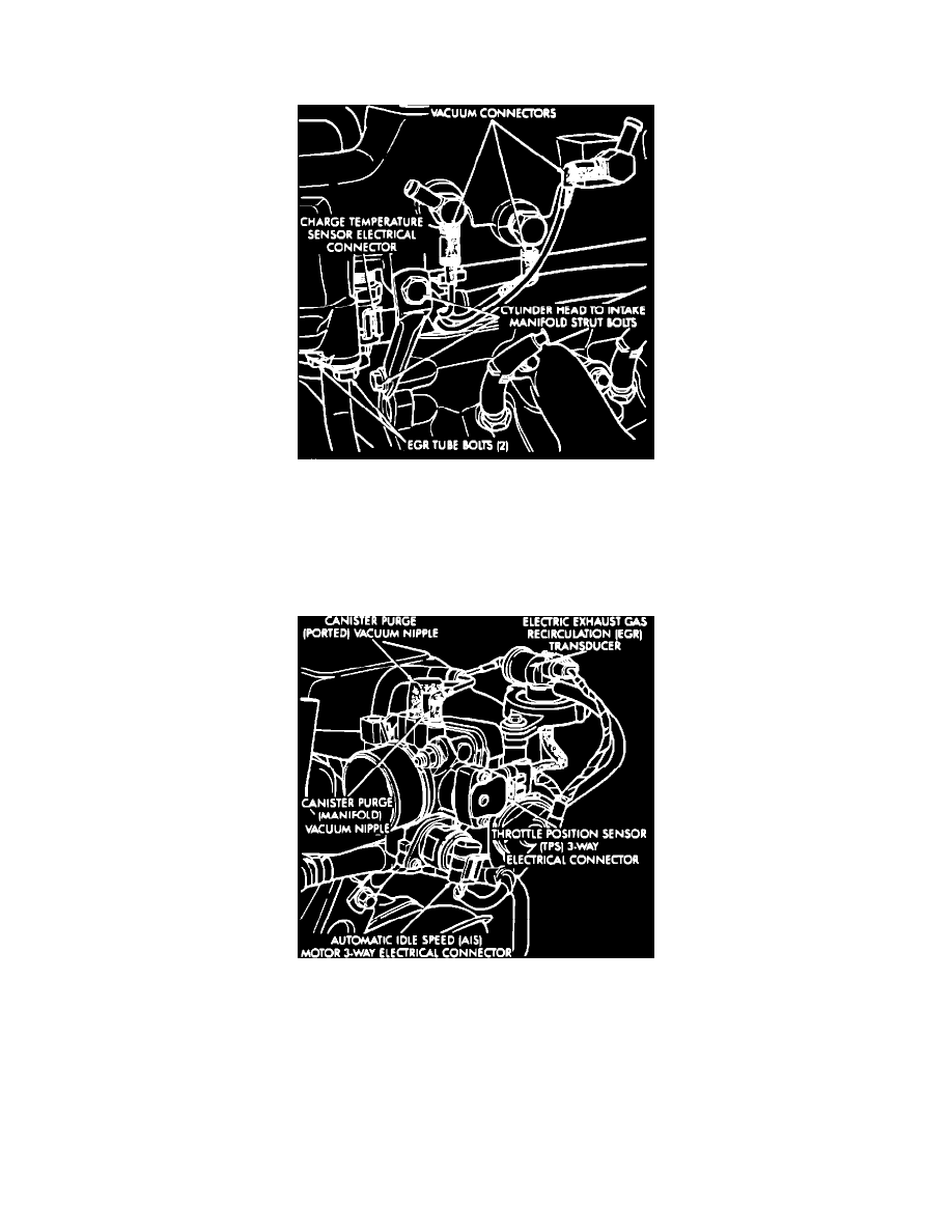
Figure 6 - MAP Sensor Electrical Connector
(16) Connect ground strap, MAP and heated oxygen sensor electrical connectors (Fig. 6).
Figure 5 - Electrical and Vacuum Connections To Intake Manifold
(17) Connect charge temperature sensor electrical connector (Fig. 5).
(18) Connect vacuum harness to intake plenum (Fig. 5). Connect PCV system and brake booster hose.
(19) On California models, using a new gasket from the parts package, connect the EGR tube flange to the intake manifold and torque to 22 N-m (200
in.lbs.).
(20) Clip wiring harness into the holes in the throttle cable bracket and intake manifold water tube bracket.
Figure 4 - Electrical and Vacuum Connection to Throttle Body
(21) Connect the wiring connectors to the throttle position sensor (TPS) and Automatic Idle Speed (AIS) motor (Fig. 4).
(22) Connect vacuum harness to throttle body (Fig. 4).