
Town & Country Van V6-201 3.3L VIN R SMFI (1990)
Automatic Shut Down (ASD) Relay: Testing and Inspection
Auto Shutdown (ASD) Relay
Main Relay testing and inspection can also be found at Powertrain Management / Computers and Control systems / Testing and Inspection / Procedures /
Diagnostic Charts / No Start (NS) Tests / NS-14 Repairing Fault "ASD Relay Circuit".
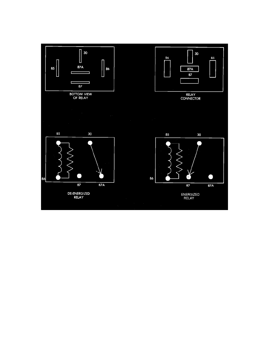
Relay Terminal Identification
ASD RELAY TERMINAL IDENTIFICATION
The following is a list of the terminal numbers, with circuit codes, and color codes, and their function:
Circuit No. Terminal No.
Color Code
Description
J1/J11
30
Red
Has battery input voltage supplied through fusible link.
Z1
87
Green/blk.
Connected to J1 circuit (terminal 30) in the energized position, supplies output voltage to fuel pump, O2
sensor, fuel injectors, and coil.
J2
86
Blue/wht.
Connected to the electromagnet, (diode) and the Single Board Engine Controller (SBEC). The SBEC
provides input voltage to relay.
K19
85
Blue/yel.
Connected to the electromagnet (diode) and grounded by the SBEC when distributor signal is present.
N/A
87A
N/A
Not used in these applications.
ASD RELAY TEST
NOTE: The ASD relay operation may be tested with the use of the DRB II scanner or equivalent. Refer to COMPUTERIZED ENGINE
CONTROLS/DIAGNOSIS AND TESTING for procedure. If no scanner is available proceed with the following test.