
Town & Country Van V6-201 3.3L VIN R SMFI (1990)
Powertrain Control Module: Description and Operation
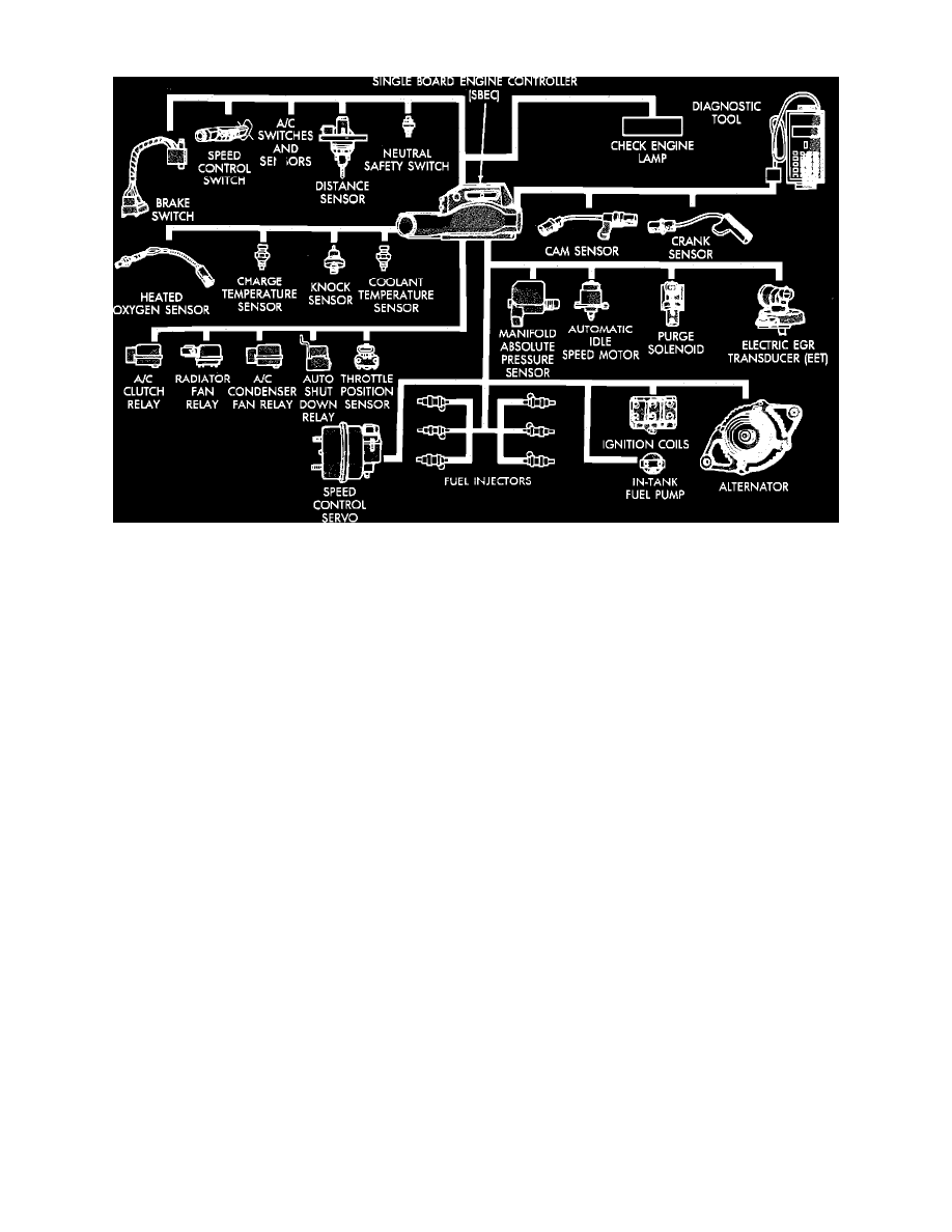
Computerized Engine Controls
The engine systems in this vehicle are controlled by a Single Board Engine Controller (SBEC). This controller provides precise air/fuel mixture control
for all driving conditions, and regulates ignition timing, emission control devices, cooling fan, charging system, and idle speed. The SBEC is a digital
pre-programmed computer that has the ability to update and revise its programming to meet changing operating conditions.
Various sensors provide necessary input for the SBEC to function correctly. These include the Manifold Absolute Pressure Sensor, Throttle Position
Sensor, Oxygen Sensor, Coolant Temperature Sensor, and Vehicle Distance Sensors. In addition to these sensors, various switches and relays are used
to carry out commands or outputs from the SBEC.
The Automatic Shutdown (ASD) relay is not located inside the SBEC, but it is turned OFF and ON by the SBEC (controls the ground). The Crank
Timing and Cam Reference Sensors send signals directly to the SBEC, and in the event that the SBEC does not receive either of these signals, the ground
is removed from the ASD circuit. If the ignition switch is ON and the engine is OFF, the SBEC will allow the ground to be applied to the ASD for
approximately 2 seconds, then if no Cam or Crank sensor signal is sensed, the SBEC removes the ground from the circuit. If the ground is removed from
the ASD relay circuit, then the ASD relay acts as an OPEN switch in the power circuits to the fuel injector, fuel pump, ignition coil, and oxygen sensor
heating element, causing a no start condition.
The SBEC tests many of its own input and output circuits. If a fault is found in any major system, this information is either stored in memory or
displayed as a light on the instrument panel. If a fault exists, the fault information can be displayed to a technician through the instrument panel CHECK
ENGINE lamp or a suitable diagnostic scan tool.
The SBEC contains a voltage regulator and converter that converts an input voltage of 12 volts to a regulated output voltage of 8 volts and 5 volts. The
8 volt output is sent to power the cam and crank sensors and the 5 volt output is used to provide power to the Throttle Position Sensor (TPS), the
Manifold Absolute Pressure (MAP) Sensor, and logic circuits.
LIMP IN MODE
This mode is a mode that is entered by the SBEC if a component or a system should fail. If the SBEC senses no data or incorrect data from the Throttle
Position Sensor (TPS), Manifold Absolute Pressure (MAP) Sensor, or Coolant Temperature Sensor, then this mode is entered and the engine controller
uses standard information instead of using information from its input and output devices. When this mode is entered the Check Engine Lamp on the
instrument panel is illuminated. The purpose of this mode is to allow the driver to operate the vehicle until the problem is fixed.