
Town & Country Van V6-229 3.8L VIN L MFI (1995)
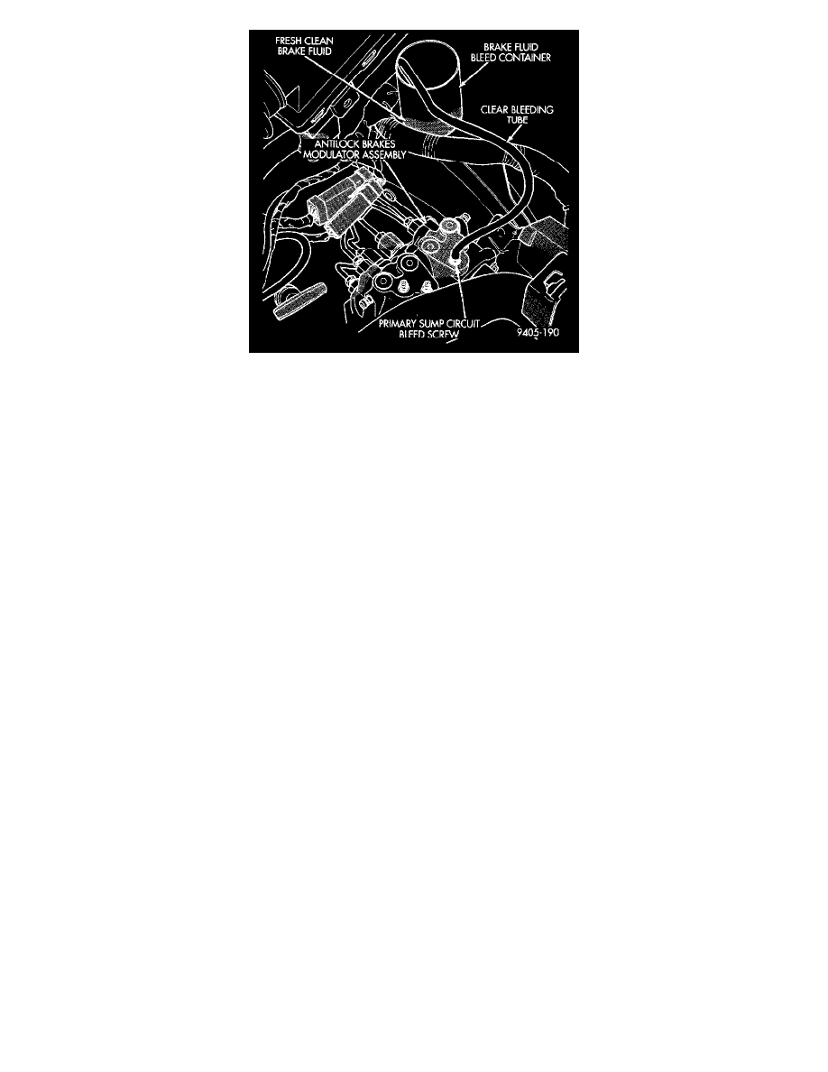
Fig. 3 BLEEDING MODULATOR ASSEMBLY PRIMARY SUMP CIRCUIT
3 MODULATOR ASSEMBLY PRIMARY SUMP CIRCUIT
1. Move clear bleed tube to primary sump bleed screw (Fig. 3). Then install bleed tube into a container partially filled with fresh clean brake fluid
(Fig. 3).
2. Pump brake pedal several times, then apply and hold a constant medium to heavy force on brake pedal.
3. Open modulator assembly primary sump circuit bleed screw (Fig. 3) at least 1 full turn. This will ensure an adequate flow of brake fluid from
the primary sump circuit.
4. Using the DRB Scan Tool, select the bleed ABS hydraulic unit mode, and then select the primary circuit. (The RF and LR solenoids will
alternately fire for five seconds). Using the DRB Scan Tool, continue to select the primary circuit until an air-free flow of brake fluid from
primary sump bleed screw is maintained or brake pedal bottoms. If an air-free flow is not maintained before brake pedal bottoms, close bleed
screw and repeat steps 2 to 4, until an air free flow is maintained.
5. After an air-free flow of brake fluid is maintained from primary sump bleed screw, close and lightly tighten bleeder screw. Then release brake
pedal. Do not release brake pedal prior to closing and tightening bleeder screw.
6. After primary sump bleed screw is closed, remove bleed hose from primary sump bleed screw.
7. Torque modulator assembly primary sump bleed screw to 9 Nm (18 in. lbs.).