
Town & Country Van V6-229 3.8L VIN L MFI (1995)
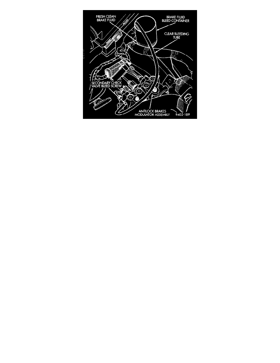
Fig. 2 BLEEDING MODULATOR ASSEMBLY SECONDARY CHECK VALVE CIRCUIT
2 MODULATOR SECONDARY CHECK VALVE CIRCUIT
1. Move clear bleed tube to secondary check valve circuit bleed screw (Fig. 2). Then install bleed tube into a container partially filled with fresh
clean brake fluid (Fig. 2).
2. Pump brake pedal several times, then apply and hold a constant medium to heavy force on brake pedal.
3. Open secondary check valve circuit bleeder screw (Fig. 2), at least 1 full turn to ensure an adequate flow of brake fluid. Continue to bleed
secondary check valve circuit until the brake pedal bottoms.
4. After brake pedal bottoms, close and tighten bleed screw and release brake pedal. Do not release brake pedal prior to closing and tightening
bleed screw.
5. Continue bleeding secondary check valve circuit, repeating steps 2 through 4, until a clear, bubble free flow of brake fluid is evident.
6. When air is bled from primary check valve circuit, tighten bleed screw and remove bleed hose from bleed screw. Do not remove bleed hose
before tightening bleed screw, air may re-enter modulator.
7. Torque modulator assembly primary bleed screw to 9 Nm (80 in. lbs.).