
Town & Country Van V6-229 3.8L VIN L MFI (1995)
Manifold Pressure/Vacuum Sensor: Testing and Inspection
NOTE: To perform a complete test of the Manifold Absolute Pressure (MAP) sensor and its circuitry, refer to appropriate Diagnostic Chart. See:
Powertrain Management/Computers and Control Systems/Testing and Inspection
TO TEST THE MAP SENSOR ONLY:
1. Inspect the rubber nipple (fitting) from the MAP sensor to the throttle body. Repair as necessary.
CAUTION: When testing the MAP sensor, be sure that the harness wires are not damaged by the test meter probes.
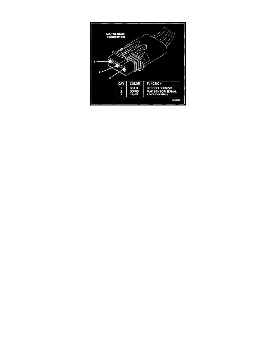
2. Test the MAP sensor output voltage at the MAP sensor connector terminal 2. With the ignition switch ON, and the engine OFF. Output voltage
should be 4 to 5 volts.
3. Test the MAP sensor output voltage at the MAP sensor connector terminal 2 at a hot, neutral idle speed condition. The voltage should drop to 1.5
to 2.1 volts.
4. Test PCM (terminal / pin-5) for the same voltage described above to verify the wire harness condition. Repair as necessary.
5. Test MAP sensor supply voltage at sensor connector terminal 3 with the ignition ON. The voltage should be approximately 5 volts (±O.5 V). 5
volts (±0.5 Volts). should also be present at terminal 6 of the PCM wire harness connector. Repair or replace the wire harness as necessary.
6. Test the MAP sensor ground circuit at sensor connector terminal 1 and PCM connector terminal / pin-4. Repair the wire harness if necessary.