
Town & Country Van 2WD V6-201 3.3L VIN R MFI (1996)
Hydraulic Control Assembly - Antilock Brakes: Service and Repair
1. Disconnect and isolate battery ground cable, then remove Hydraulic Control Unit (HCU) 10-way and 2-way connectors from bracket on lefthand
strut tower.
2. Disconnect both connectors from wiring harness and HCU pigtail retaining straps from master cylinder brake tubing.
3. To prevent loss of brake fluid from master cylinder, prop brake pedal in any position beyond first inch of travel.
4. Raise and support vehicle, then clean HCU thoroughly with suitable brake parts cleaning solvent.
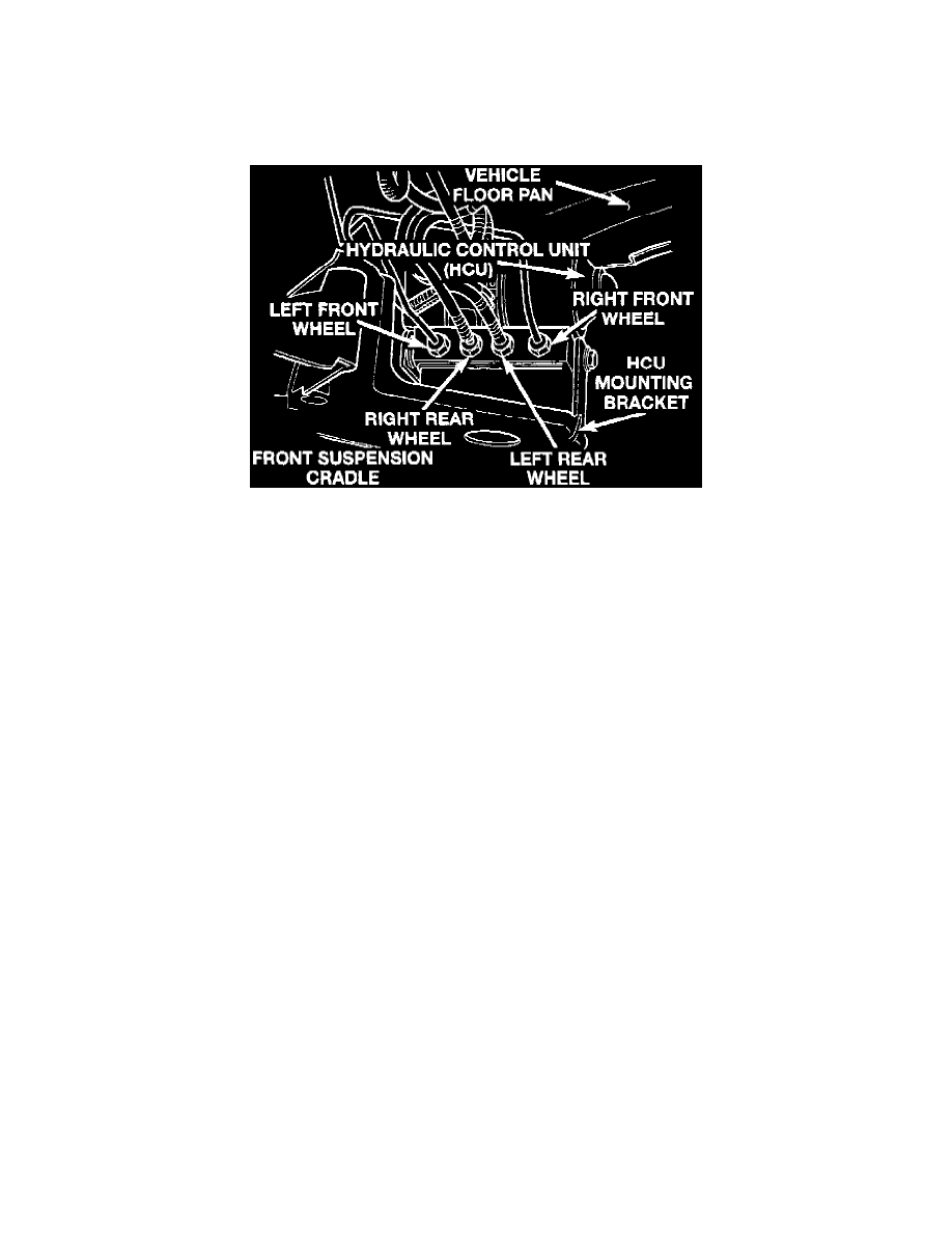
HCU Valve Block Brake Tube Connections.
5. Remove four brake tubes from HCU valve block, then disconnect two master cylinder brake tubes at HCU.
6. Remove bolts securing HCU bracket to suspension crossmember, then remove HCU and bracket as an assembly. Carefully pull HCU wiring
pigtail through retaining straps.
7. Reverse procedure to install, noting the following:
a. Do not use any bolts other than original or original equipment type to secure HCU mounting bracket to crossmember. Torque bolts to
21 ft. lbs.
b. Ensure four brake tubes are installed in correct positions on HCU valve block.
c. Torque all hydraulic line fittings to 12 ft. lbs.
d. Bleed brake system as described in this chapter, then road test vehicle to ensure ABS and base brake systems function properly.