
Town & Country Van AWD V6-230 3.8L VIN L SMFI (1998)
Junction Block Terminal Pins
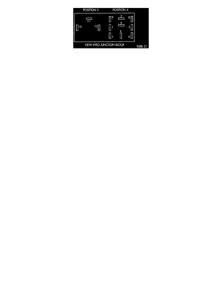
The Combination Flasher/DRL is a module providing turn signal, hazard warning, and daytime running light functions, and has been designed
with internal relays to take advantage of low current switching requirements in the vehicle. It is plugged into the junction block at positions 3
and 4 where all wiring associated with its operation is terminated. The Junction Block is adjacent to and left of the steering column of the
vehicle. To gain access to the device, remove the lower steering column cover and knee blocker.
The combination flasher/DRL may be operated in its hazard warning mode either with or without the ignition circuit being active. However, in
order to operate in the turn signal mode or the DRL mode, the ignition circuit must be completed to the module.
While the combination flasher portion is idle, there is no current drawn through the module. The device does not become active in the turn
signal or hazard warning modes until a signal ground circuit is supplied to either of the turn signal inputs or the hazard warning input. With the
ignition OFF, there is no current drawn through the module.
While the ignition is ON, the front turn signal filaments are illuminated steadily thus providing the DRL function. The DRL function may be
inhibited by applying a signal ground input from either the park brake circuit or the headlamp relay activation circuit.
Typical flash rate for the flasher is 90 flashes per minute. When a lamp is burnt out for a given side of the vehicle or a wire is open to a lamp,
the flash rate will increase to 180 flashes per minute when in the turn signal mode. When in the hazard warning signal mode the flash rate
remains at 90 flashes per minute.
Turn signal inputs that actuate the flasher are low current grounds, each could draw a maximum of 300 mA, and are provided to the flasher
through the Junction Block from the multi-function switch that is mounted to the steering column. The hazard warning signal input is a low
current ground that could draw a maximum of 600 mA. through the multi-function switch.