
Town & Country Van AWD V6-230 3.8L VIN L SMFI (1998)
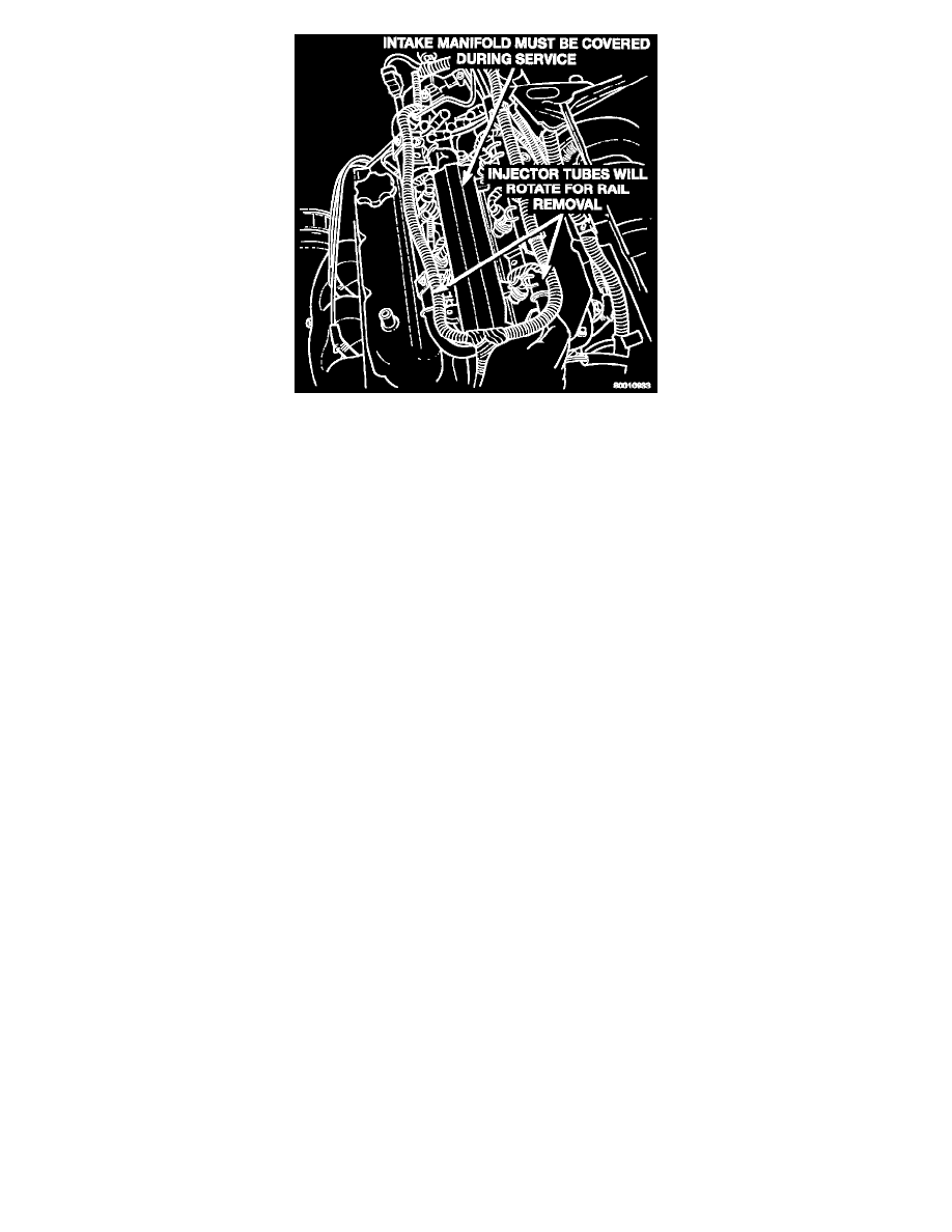
Fig 54 Fuel Rail Removal
19. Remove fuel rail. Be careful not to damage the injector 0-rings upon removal from their ports (Fig. 54).
INSTALLATION
1. Ensure injector holes are clean. Replace 0-rings if damaged.
2. Lubricate injector 0-rings with a drop of clean engine oil to ease installation.
3. Put the tip of each injector into their ports.
-
Push the assembly into place until the injectors are seated in the ports.
4. Install the fuel rail mounting bolts.
-
Tighten bolts to 22 Nm (200 in lb) torque (Fig. 52).
5. Install fuel tube retaining bracket screw.
-
Tighten screw to 4 Nm (35 in lb) torque.
6. Connect electrical connectors to camshaft position sensor and engine coolant temperature sensor.
7. Remove covering on lower intake manifold and clean surface.
8. Place intake manifold gasket on lower manifold.
-
Put upper manifold into place and install bolts finger tight.
9. Install the generator bracket to intake manifold bolt and the cylinder head to intake manifold strut bolts
-
Do not tighten.
10. Following the tightening sequence in (Fig. 51), tighten intake manifold bolts to 28 Nm (250 in lb) torque.
11. Tighten generator bracket to intake manifold bolt to 54 Nm (40 ft lb) torque.
12. Tighten the cylinder head to intake manifold strut bolts to 54 Nm (40 ft lb) torque.
13. Connect ground strap and MAP sensor electrical connector.
14. Connect vacuum harness to intake plenum. Connect PCV system hoses.
15. Using a new gasket, connect the EGR tube to the intake manifold plenum.
-
Tighten screws to 22 Nm (200 in lb) torque.
16. Connect electrical connectors to the TPS and idle air control motor.
17. Connect vacuum harness to throttle body.
18. Install the Direct Ignition System (DIS) coils.
-
Tighten fasteners to 12 Nm (105 in lb) torque.
19. Install fuel hose quick connector fitting to chassis tubes.
-
Push the fitting onto the chassis tube until it clicks into place.
-
Pull on the fitting to ensure complete insertion.
20. Install throttle cable and speed control cable (if equipped).
21. Install air inlet resonator.
22. Connect negative cable to battery.
CAUTION: When using the ASD Fuel System Test, the ASD relay and fuel pump relay remain energized for 7 minutes or until the test is
stopped, or until the ignition switch is turned to the Oft position.
23. With the ignition key in ON position, access the DRB scan tool ASD Fuel System Test to pressurize the fuel system. Check for leaks.