
Town & Country Van AWD V6-230 3.8L VIN L SMFI (1998)
Ignition Coil: Testing and Inspection
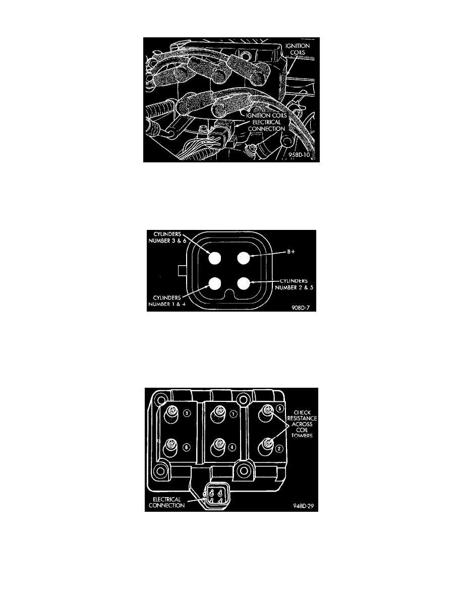
Fig 18 Ignition Coil Electrical Connector
Coil 1 fires cylinders 1 and 4, coil 2 fires cylinders 2 and 5, and coil 3 fires cylinders 3 and 6. Each coil tower is labeled with the number of the
corresponding cylinder.
1. Disconnect the electrical connector from the coil pack (Fig. 18).
Fig 19 Ignition Coil Terminal ID
2. Measure the primary resistance of each coil. At the coil, connect an ohmmeter between the B+ pin and the pin corresponding to the cylinders in
question (Fig 19).
-
Resistance on the primary side of each coil should be 0.45 - 0.65 ohm at 21° to 27°C (70° to 80°F).
-
A coil that has not been allowed to cool off, would result in inaccurate measurement results.
-
Replace the coil if resistance is not within tolerance.
Fig 20 Checking Ignition Coil Secondary Resistance
3. Remove ignition cables from the secondary towers of the coil. Measure the secondary resistance of the coil between the towers of each individual
coil (Fig. 20).
-
Secondary resistance should be 7,000 to 15,800 ohms.
-
Replace the coil if resistance is not within tolerance.