
Town & Country Van AWD V6-230 3.8L VIN L SMFI (1998)
Horn Relay: Testing and Inspection
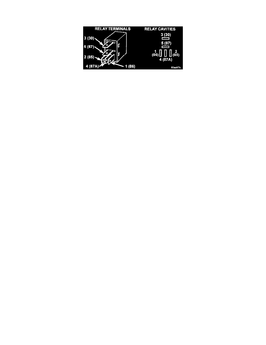
1. Remove horn relay.
Horn Relay
2. Using ohmmeter, test between relay connector terminals 85 to 86 for 70 to 75 ohms resistance. If resistance not OK, replace relay.
3. Test for continuity between ground and terminal 85 of horn relay.
a. When the horn switch is not depressed, no continuity should be present.
b. Continuity to ground when horn switch is depressed.
c. If continuity is not correct repair horn switch or wiring as necessary.
4. Using voltmeter, test voltage at:
a. Terminals 30 and 86 of the horn relay to body ground.
b. If NO voltage check fuse 7 of the BCM.
c. If incorrect voltage repair as necessary.
5. Insert a jumper wire between terminal 30 and 87 of the power distribution center.
a. If horn sounds replace relay.
b. If the horn does not sound, install horn relay and refer to Horn Test.
Horns Will Not Sound
Check horn fuse 6 in the Power Distribution Center and fuse 7 in the Junction Block. If fuse is blown refer to FUSE BLOWN. If fuse is OK, refer
to FUSE OK.
Fuse Blown
1. Verify condition of battery terminals and voltage. If battery connections and battery charge is OK proceed to Step 2.
2. Using a voltmeter, test for battery voltage at both sides of horn fuse 7. If voltage is OK, on both sides of fuse, proceed to Fuse OK. If voltage is
OK, on one side of fuse, the fuse is blown, proceed to Step 3.
3. Using a suitable ammeter in place of the fuse, test amperage draw of the horn circuit. If amperage draw is greater than 20 amps without the
horn switch depressed, a grounded circuit exists between the fuse and the horn relay. Proceed to Step 4. If amperage draw is greater than 20
amps with the horn switch depressed, a grounded circuit exists between the horn relay and the horn. Proceed to step Step 5.
4. Remove the horn relay from the Junction Block. If the amperage draw drops to 0 amps, the horn switch or circuit is shorted. If the amperage
draw does not drop to 0 amps, repair short at the Junction Block.
5. Disengage a wire connector from one of the horns. If amperage drops and the connected horn sounds, replace the faulty horn. If amperage does
not drop with both horns disconnected and the horn switch depressed, proceed to Step 6.
6. Using a continuity tester, with the horns disconnected test continuity of the X2 cavity of the horn relay to ground. If continuity is detected, the
circuit is grounded between the Junction Block and the horns. Locate and repair pinched harness.
Fuse OK
1. Remove the horn relay from the Junction Block.
2. Using a continuity tester, Depress horn switch and test continuity from the X3 cavity of the horn relay to ground.
a. If continuity is detected, proceed to Step 3.
b. If NO continuity, proceed to Step 4.
3. Using a suitable jumper wire, jump across the fuse F62 cavity and the X2 cavity of the horn relay in the Junction Block.
a. If the horn sounds, replace the horn relay.
b. If the horn does not sound, proceed to Step 4.
4. Remove airbag"horn pad from steering wheel.
5. Test continuity across horn switch connectors with horn switch depressed.
a. If continuity is detected, repair open circuit between the relay and the horn switch.
b. If NO continuity, replace airbag cover.
6. Install horn relay into Junction Block.
7. Disengage wire connectors from horns.