
Town & Country Van AWD V6-230 3.8L VIN L SMFI (1998)
Camshaft Position Sensor: Description and Operation
Fig 9 Camshaft Position Sensor
PURPOSE
-
Sensor provides PCM with cylinder identification.
-
PCM uses sensor input to determine fuel injection sequence and ignition timing.
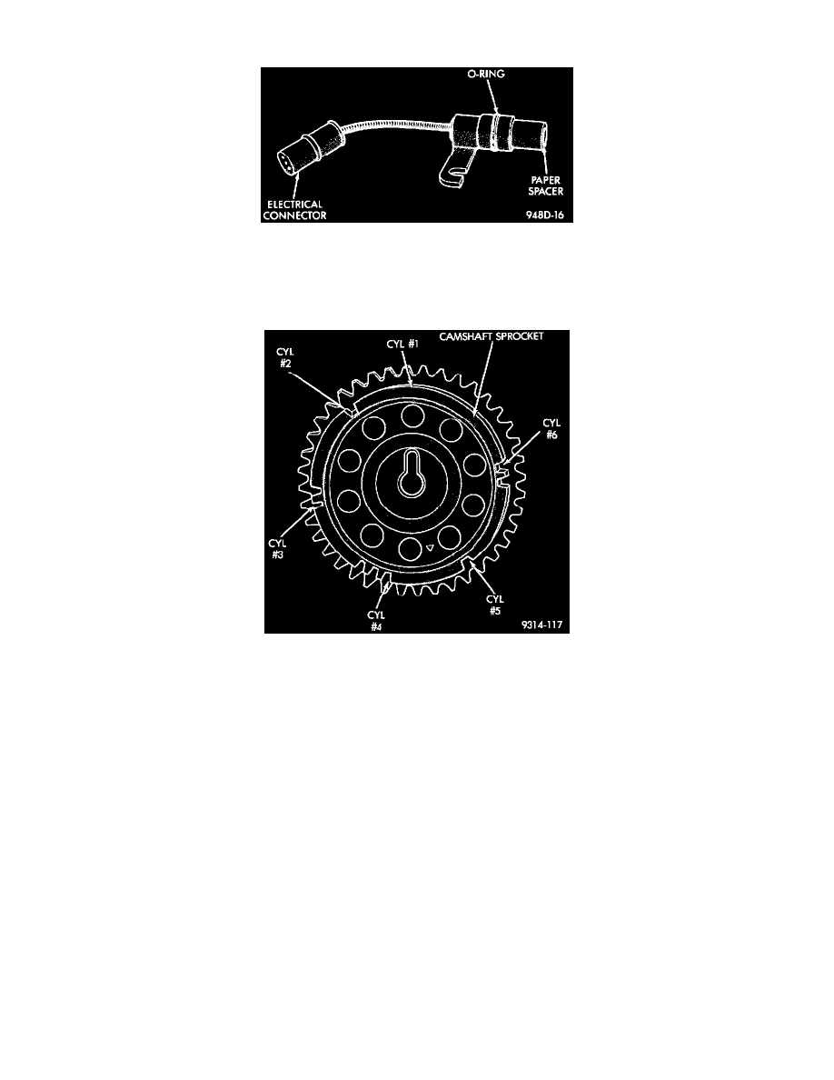
Fig 10 Camshaft Sprocket
OPERATION
The sensor generates pulses as groups of notches on the camshaft sprocket pass underneath it (Fig. 10).
The PCM keeps track of crankshaft rotation and identifies each cylinder by the pulses generated by the notches on the camshaft sprocket.
-
Four crankshaft pulses follow each group of camshaft pulses.
When the PCM receives 2 cam pulses followed by the long flat spot on the camshaft sprocket, it knows that the crankshaft timing marks for
cylinder 1 are next (on driveplate). When the PCM receives one camshaft pulse after the long flat spot on the sprocket, cylinder number 2
crankshaft timing marks are next. After 3 camshaft pulses, the PCM knows cylinder 4 crankshaft timing marks follow. One camshaft pulse after the
3 pulses indicates cylinder 5. The 2 camshaft pulses after cylinder 5 signals cylinder 6 (Fig. 10). The PCM can synchronize on cylinders 1 or 4.
When metal aligns with the sensor, voltage goes low (less than 0.3 volts). When a notch aligns with the sensor, voltage switches high (5.0 volts).
As a group of notches pass under the sensor, the voltage switches from low (metal) to high (notch) then back to low. The number of notches
determine the amount of pulses. If available, an oscilloscope can display the square wave patterns of each timing event.
Top Dead Center (TDC) does not occur when notches on the camshaft sprocket pass below the cylinder. TDC occurs after the camshaft pulse (or
pulses) and after the 4 crankshaft pulses associated with the particular cylinder. The arrows and cylinder call outs on Figure 4 represent which
cylinder the flat spot and notches identify, they do not indicate TDC position.