
Town & Country Van AWD V6-230 3.8L VIN L SMFI (1998)
Crankshaft Position Sensor: Description and Operation
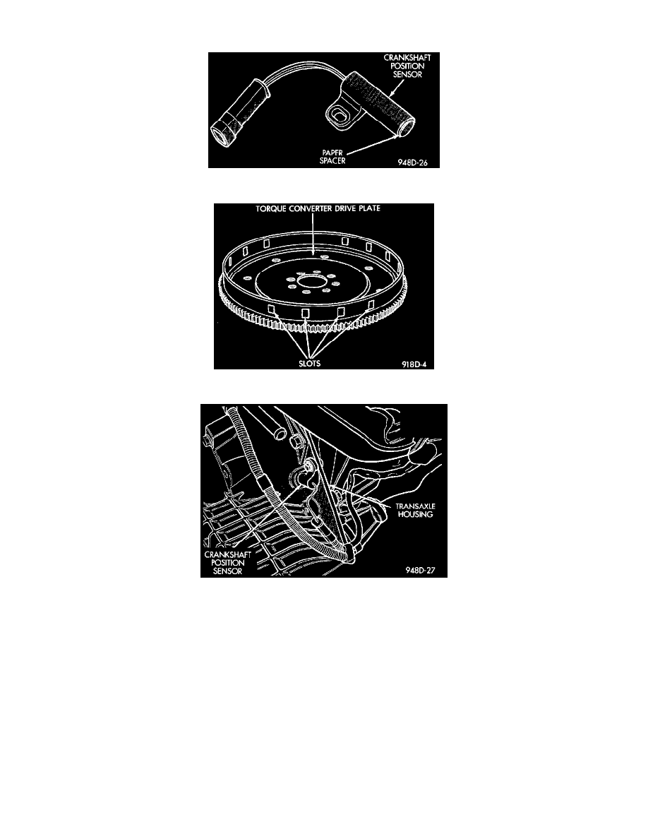
Fig 6 Crankshaft Position Sensor
Fig 7 Timing Slots
Fig 8 Crankshaft Position Sensor
OPERATION
The crankshaft position sensor detects slots cut into the transmission driveplate extension (Fig. 7). There are 3 sets of slots. Each set contains 4
slots, for a total of 12 slots.
Basic timing is set by the position of the last slot in each group. Once the Powertrain Control Module (PCM) senses the last slot, it determines
crankshaft position (which piston will next be at TDC) from the camshaft position sensor input. The 4 pulses generated by the crankshaft position
sensor represent the 69°, 49°, 29°, and 9° BTDC marks. It may take the PCM one engine revolution to determine crankshaft position.
The PCM uses crankshaft position reference to determine injector sequence, ignition timing and the presence of misfire. Once the PCM determines
crankshaft position, it begins energizing the injectors in sequence.
The crankshaft sensor is located on the passengers side of the transmission housing, above the differential housing (Fig. 8). The bottom of the
sensor is positioned next to the drive plate.
CIRCUIT OPERATION
Circuit K7 supplies 8 volts from the Powertrain Control Module (PCM) to the crankshaft position sensor. The K7 circuit originates at cavity 44 of