
Voyager L4-2.4L VIN B (2001)
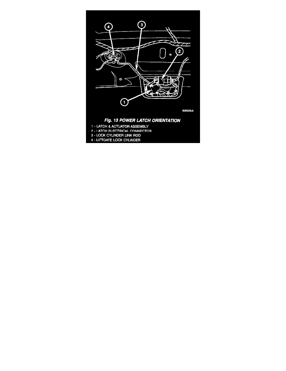
Fig.13 Power Latch Orientation
3. Disconnect the power latch electrical connector.
4. Remove the three latch retaining bolts.
5. Grab the latch assembly and unhook the key cylinder link rod from the key cylinder.
6. Place the latch assembly on a bench and locate the three wires leading from the actuator portion of the latch assembly.
7. Disengage the main connector retaining push pins from the latch actuator housing.
8. Back the three wires out of the main latch electrical connector. Refer to the wiring for detailed instructions.
9. Flip the latch assembly over and remove the latch actuator retaining screw(s).
10. Remove the latch actuator from the latch assembly.
INSTALLATION
1. Install the latch actuator on the latch assembly.
2. Install the three latch actuator retaining screws. Torque the screws to 4 in. lbs..
3. Install the three wires in the main latch electrical connector. Refer to the wiring for detailed instructions.
NOTE: Be certain wires are reinstalled in the correct wire cavities. Failure to do so could result in damage to the latch actuator. Refer to Wiring
Diagrams if previous notes were not made.
4. Secure the main connector retaining push pins on the latch actuator housing.
5. Grab the latch assembly and hook the key cylinder link rod on the key cylinder.
6. Position the latch and install the three latch retaining bolts. Torque to 10 Nm (90 in. lbs.).
7. Connect the power latch electrical connector.
8. Install the lower liftgate trim panel. Refer to Body for the procedure.
9. Connect the negative battery cable.