
Voyager V6-3.0L VIN 3 (2000)
Memory Positioning Systems: Testing and Inspection
Seat and Recliner Position Sensing
Seat and recliner position sense ground reference circuit P28 BR/RD feed is from the memory seat/mirror module (cavity 10) 21-way connector to each
of the position sense connectors.
Seat and recliner position sense +5 volt feed circuit P29 BR/WT feed is from the memory seat/mirror module (cavity 20) 21-way connector to each of
the position sense connectors.
To test for the presence of a sense voltage, a volt meter must be used as follows:
-
Connect the negative probe to the P28 circuit (cavity 10) of the 21-way connector.
-
Connect the positive probe to the P29 circuit (cavity 20) of the 21-way connector and verify a voltage reading between 3.5 and 5 volts when a seat
or recliner switch is activated. An internal timer in the Memory Seat/Mirror Module (MSMM) regulates the length of time this voltage stays active
i.e., 3 seconds from the time that the switch was activated, unless the switch is held or while the transmission is out of PARK. If the voltage is less
than 3.5, there is a fault in the system that is drawing it down. To troubleshoot this circuit, disconnect the 25-way connector from the MSMM (this
removes all of the vehicle mirror circuitry). If the voltage is still less than 3.5, disconnect each of the position sense connectors from each of the
motors. If the voltage remains less than 3.5, replace the MSMM. If the voltage increases when a motor is disconnected from the system,
determine if the fault is in the wiring or the motor assembly. Repair or replace the wire harness assembly as needed. If the fault is in the motor
position sensing potentiometer, replace the track assembly.
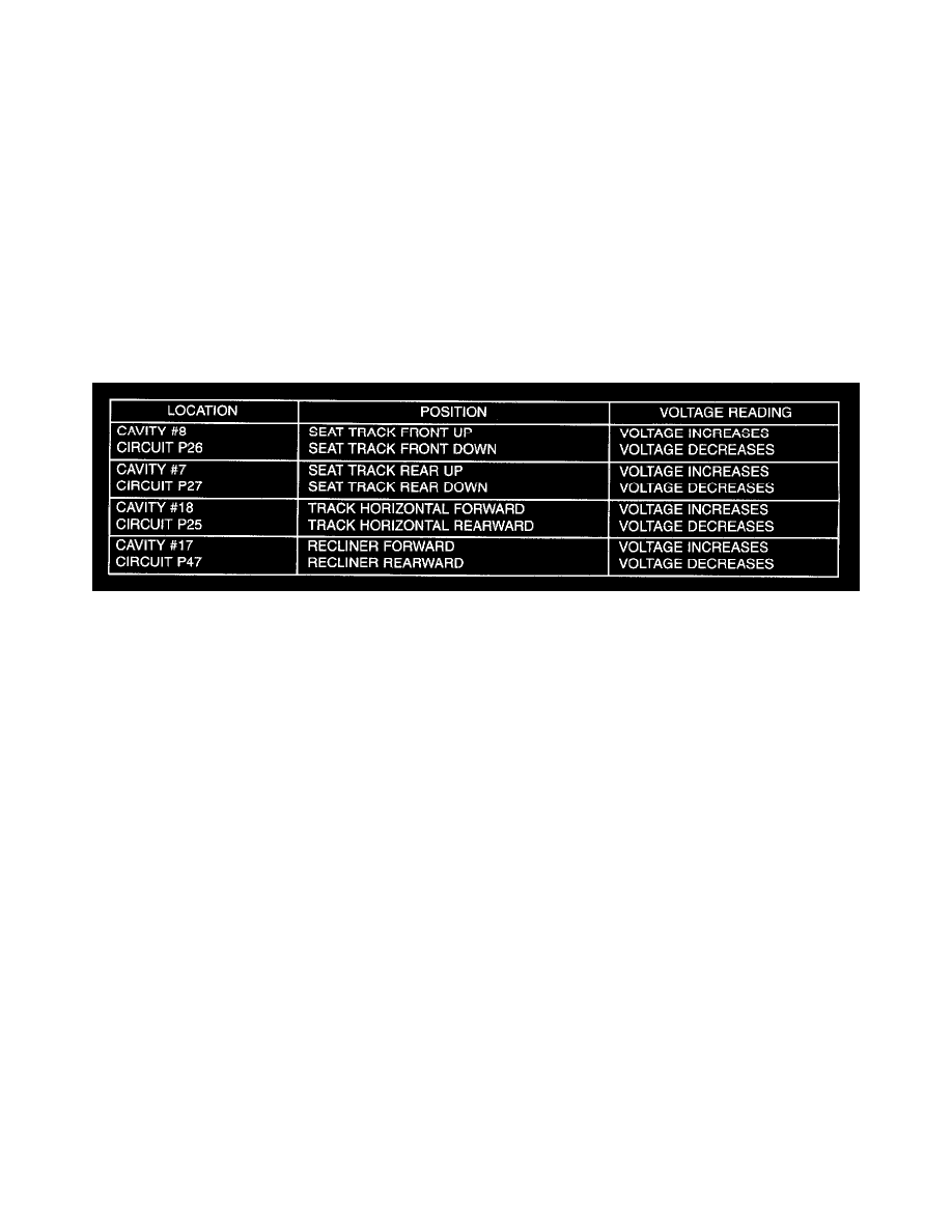
Seat Actuations Table
-
The potentiometers built onto the motor end-bell provide voltages to the MSMM through the 21-way connector, which change as follows,
corresponding to the given seat actuations. Refer to Seat Actuations Table