
Voyager V6-3.3L VIN 3 Flex Fuel (2003)
Hydraulic System Junction Block: Service and Repair
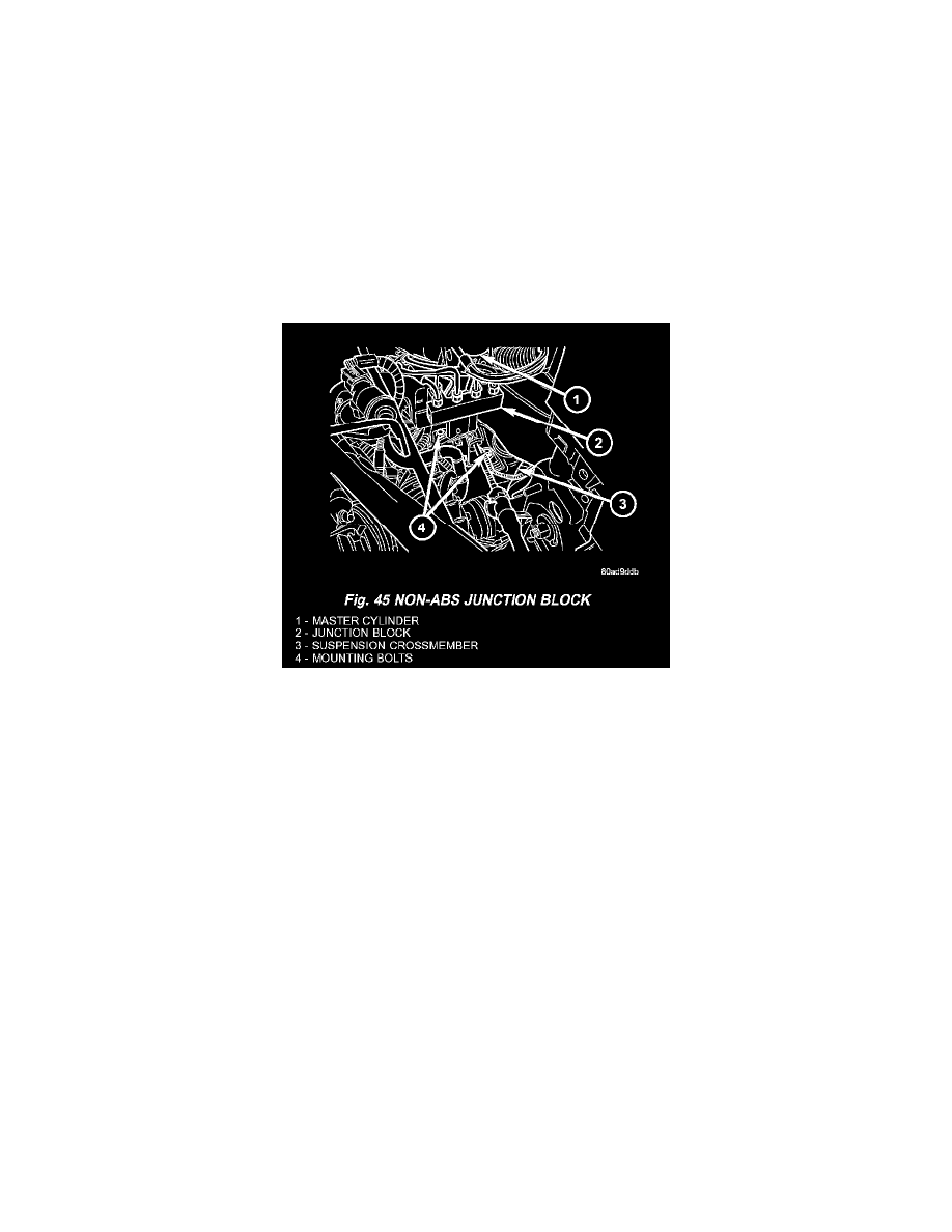
REMOVAL - NON-ABS JUNCTION BLOCK
1. Using a brake pedal depressor, move and lock the brake pedal to a position past its first 1 inch of travel. This will prevent brake fluid from
draining out of the master cylinder when the brake tubes are removed from the junction block.
2. Disconnect the battery negative cable.
3. If the vehicle is equipped with speed control, perform the following:
a. Disconnect the battery positive cable.
b. Remove the battery.
c. Disconnect the vacuum hose connector at the tank built into the battery tray.
d. Remove the screw securing the coolant filler neck to the battery tray.
e. Remove the battery tray.
f.
Remove the fasteners and move the speed control servo off to the side, out of the way.
CAUTION: Before removing the brake tubes from the junction block, the junction block and the brake tubes must be thoroughly cleaned.
This is required to prevent contamination from entering the brake hydraulic system.
4. Remove the four chassis brake tubes from the top of the junction block.
5. Remove the primary and secondary brake tubes from the top of the junction block.
6. Remove the bolts attaching the junction block mounting bracket to the front suspension crossmember, then remove the junction block.
INSTALLATION - NON-ABS JUNCTION BLOCK
1. Install the junction block and mounting bracket on the front suspension crossmember. Install the mounting bolts and tighten to a torque of 28 Nm
(250 in. lbs.).
2. Install the primary and secondary brake tubes from the master cylinder in their ports. Tighten tube nuts to a torque of 17 Nm (145 in. lbs.). Take
care not to twist tubes when tightening tube nuts. They must be properly positioned to allow free movement with rubber isolated suspension
crossmember.
3. Install the four chassis brake tubes into the outlet ports of the junction block. Tighten all 6 tube nuts to a torque of 17 Nm (145 in. lbs.).
4. If the vehicle is equipped with speed control, perform the following:
a. Install the speed control servo with its mounting nuts.
b. Connect the wiring harness to the speed control servo.
c. Install the battery tray.
d. Install the screw securing the coolant filler neck to the battery tray.
e. Reconnect the vacuum hose connector at the tank built into the battery tray.
f.
Install the battery.
g. Install the battery shield.
5. Remove the brake pedal holder.
6. Connect negative cable back on negative post of the battery.
7. Bleed the brake system thoroughly to ensure that all air has been expelled from the hydraulic system.
8. Road test the vehicle to verify proper operation of the brake system.