
Voyager V6-3.3L VIN 3 Flex Fuel (2003)
Remote Switch: Testing and Inspection
WARNING: ON VEHICLES EQUIPPED WITH AIRBAGS, REFER TO ELECTRICAL, RESTRAINTS BEFORE ATTEMPTING ANY
STEERING WHEEL, STEERING COLUMN, OR INSTRUMENT PANEL COMPONENT DIAGNOSIS OR SERVICE. FAILURE TO TAKE
THE PROPER PRECAUTIONS COULD RESULT IN ACCIDENTAL AIRBAG DEPLOYMENT AND POSSIBLE PERSONAL INJURY.
Any diagnosis of the Audio system should begin with the use of the DRB III(R) diagnostic tool. For information on the use of the DRB III(R), refer to
the appropriate Diagnostic.
Refer to the appropriate wiring information. The wiring information includes wiring diagrams, proper wire and connector repair procedures, details of
wire harness routing and retention, connector pin-out information and location views for the various wire harness connectors, splices and grounds.
1. Disconnect and isolate the battery negative cable. Wait two minutes for the airbag system capacitor to discharge before further service.
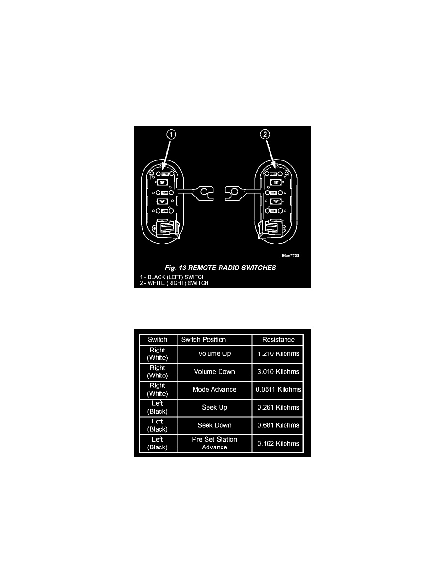
Fig.13 Remote Radio Switches
2. Remove the remote radio switch(es) from the steering wheel. (Refer to ELECTRICAL/AUDIO/REMOTE SWITCHES - REMOVAL).
Remote Radio Switch Test
3. Use an ohmmeter to check the switch resistance as shown in the Remote Radio Switch Test table.
NOTE: The right remote radio switch back is white in color. The left switch back is black in color. The right/left remote radio switch orientation
is with the steering wheel installed, and driver in drivers seat.
4. If the switch resistance checks OK, go to Step 5. If not OK, replace the faulty switch.
5. Check for continuity between the ground circuit cavity of the switch wire harness connector and a good ground. There should be continuity. If OK,
go to Step 6. If not OK, repair the open circuit as required.
6. Unplug the 24-way white wire harness connector from the Body Control Module (BCM). Check for continuity between the radio control circuit