
Nubira CDX Wagon L4-2.0L DOHC D-TEC MFI (2000)
Malfunction Indicator Lamp: Testing and Inspection
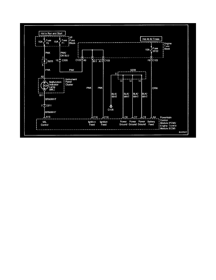
No Malfunction Indicator Lamp
Circuit Description
When the ignition is turned ON, the Malfunction Indicator Lamp (MIL) will be turned on and remain on until the engine is running, if no Diagnostic
Trouble Codes (DTC) are stored. Battery voltage is supplied through the ignition switch directly to the MIL telltale. The powertrain control module
(PCM)/engine control module (ECM) controls the MIL by providing a ground path through the MIL control circuit to turn on the MIL.
Diagnostic Aids
An open ignition F5 fuse will cause the entire cluster to be inoperative, and may set DTC P1625.
Check the battery and ignition feed circuits for poor connections if the MIL is intermittent.
Any circuitry, that is suspected as causing an intermittent complaint, should be thoroughly checked for backed-out terminals, improper mating, broken
locks, improperly formed or damaged terminals, poor terminals-to-wiring connections or physical damage to the wiring harness.
Test Description
Number(s) below refer to the step number(s) on the diagnostic table.
1. The On-Board Diagnostic (OBD II) System Check prompts the technician to complete some basic checks and store the freeze frame and failure
records data on then scan tool, if applicable. This creates an electronic copy of the data taken when the malfunction occurred. The information is
stored in the scan tool for later reference.
3. Connections that are suspected of being faulty should be thoroughly checked as described in the diagnostic aids
4. If the engine fails to start and the MIL is inoperative, then the fault can be isolated to either the PCM/ECM ignition feed, The battery feed, or a
poor ground at the engine block, or the PCM/ECM.
6. Probing the MIL circuit with a test light to ground stimulates the PCM/ECM's control of the MIL. If the MIL illuminates, then the malfunction can
be isolated to the control of the MIL or a poor connection at the MIL terminal to the PCM/ECM. Connections that are suspected of being faulty
should be thoroughly checked as described in the diagnostic aids.
8. It takes very little resistance for the battery and ignition feed circuits to cause an intermittent condition and should also be checked for a poor
connection as described in diagnostic aids.
11. Before replacing the PCM/ECM, check for backed-out terminals, improper mating, broken locks, improperly formed or damaged terminals, poor
terminal-to-wiring harness. Replacement PCM/ ECM's must be reprogrammed. Refer to the latest Techline information for reprogramming
procedures.
20. PCM/ECM grounds will only cause a problem if all of the grounds are not making a good connection. If a PCM/ECM ground problem is
suspected, the most probable place to check is where all the grounds meet, at the engine block.