
Testing and Inspection for Fuel Pump Relay - Helpful Information
Fuel Pump Relay: Testing and Inspection
Relay Test
Relay Terminals
NOTES:
-
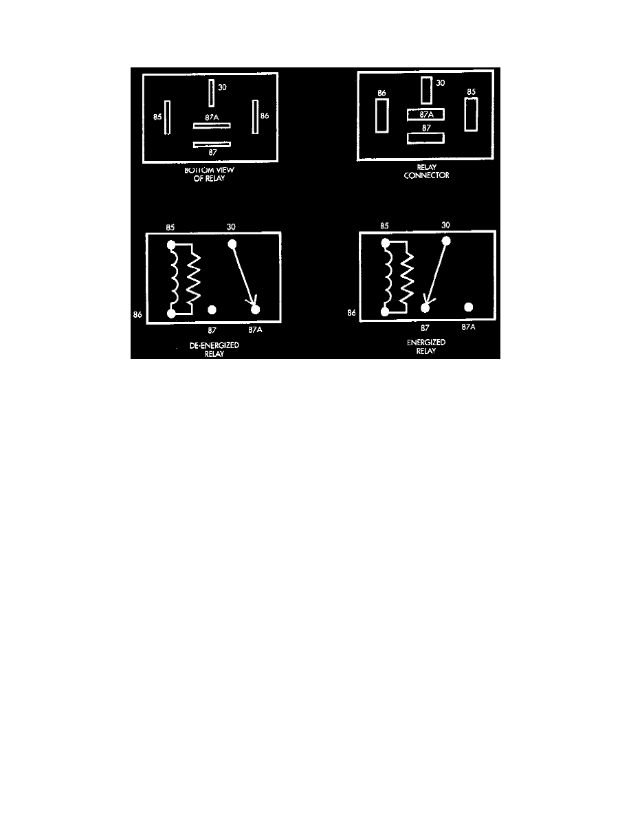
The relay terminal numbers can be found on the bottom of the relay.
-
Along with supplying voltage to the fuel pump relay contacts, circuit A14 splices to supply voltage to the contact side of the ASD relay.
-
Circuit F18 splices to supply battery voltage to the coil sides of the ASD relay and fuel pump relay.
TERMINAL ID
-
Terminal number 30 is connected to battery voltage and can be switched or B+ (hot) at all times.
-
The center terminal number 87A is connected (a circuit is formed) to terminal 30 in the de-energized (normally OFF) position.
-
Terminal number 87 is connected (a circuit is formed) to terminal 30 in the energized (ON) position. Terminal number 87 then supplies battery
voltage to the component being operated.
-
Terminal number 86 is connected to a switched (+) power source.
-
Terminal number 85 is grounded by the Powertrain Control Module (PCM).
TESTING
1. Remove relay before testing.
2. Using an ohmmeter, perform a resistance test between terminals 85 and 86. Resistance value (ohms) should be 75 +/- 5 ohms for resistor equipped
relays.
3. Connect the ohmmeter between terminals number 87A and 30. Continuity should be present at this time.
4. Connect the ohmmeter between terminals number 87 and 30. Continuity should not be present at this time.
5. Use a set of jumper wires (16 gauge or smaller). Connect one jumper wire between terminal number 85 (on the relay) to the ground side (-) of a 12
volt power source.
6. Attach the other jumper wire to the positive side (+) of a 12V power source. Do not connect this jumper wire to relay at this time.
CAUTION: Do not allow the ohmmeter to contact terminals 85 or 86 during these tests. Damage to ohmmeter may result.
7. Attach the other jumper wire (12V +) to terminal number 86. This will activate the relay. Continuity should now be present between terminals
number 87 and 30. Continuity should not be present between terminals number 87A and 30.
8. Disconnect jumper wires from relay and 12 volt power source.
If continuity or resistance tests did not pass, replace relay.