
2500 4x2 Pickup L6-359 5.9L DSL Turbo (1994)
holder (Figure 7).
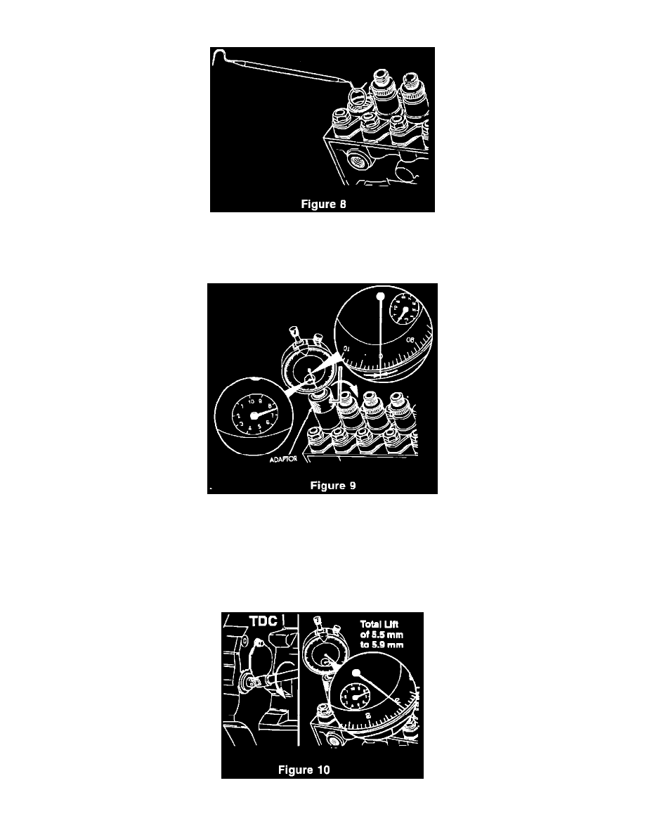
9.
Using a pick, remove the copper delivery valve washer from the top of the pumping element. Be careful not to scratch the top of the plunger/barrel
assembly during this process. Discard the used delivery valve washer. A new washer, P/N 4778483, will be used during reassembly (Figure 8).
10.
Install the dial indicator adaptor, Miller P/N 6842, in place of the # 1 delivery valve holder and tighten finger tight.
11.
Loosen the set screw on the dial indicator adaptor and install the dial indicator, Miller P/N 6859, into the adaptor. Position the dial indicator to
read between 7.0 and 9.0 mm and tighten the set screw (Figure 9).
NOTE:
THE DIAL INDICATOR IS CAPABLE OF MEASURING FROM 0-20.00 MM LIFT. THE SMALL INNER DIAL IS MARKED IN
INCREMENTS OF 1 MM. THE LARGE OUTER DIAL IS MARKED IN INCREMENTS OF 0.01 MM. ONE REVOLUTION OF THE OUTER
DIAL IS EQUAL TO 1 MM. THE INNER DIAL ONLY INDICATES 0-10 MM, BUT WILL ROTATE TWICE AS THE INDICATOR GOES
THROUGH THE FULL RANGE.
12.
Using the engine barring tool, Miller P/N 7471B, rotate the engine in the direction opposite normal direction of engine rotation (counterclockwise