
2500 4x2 Pickup L6-359 5.9L DSL Turbo (1994)
Blower Motor Relay: Description and Operation
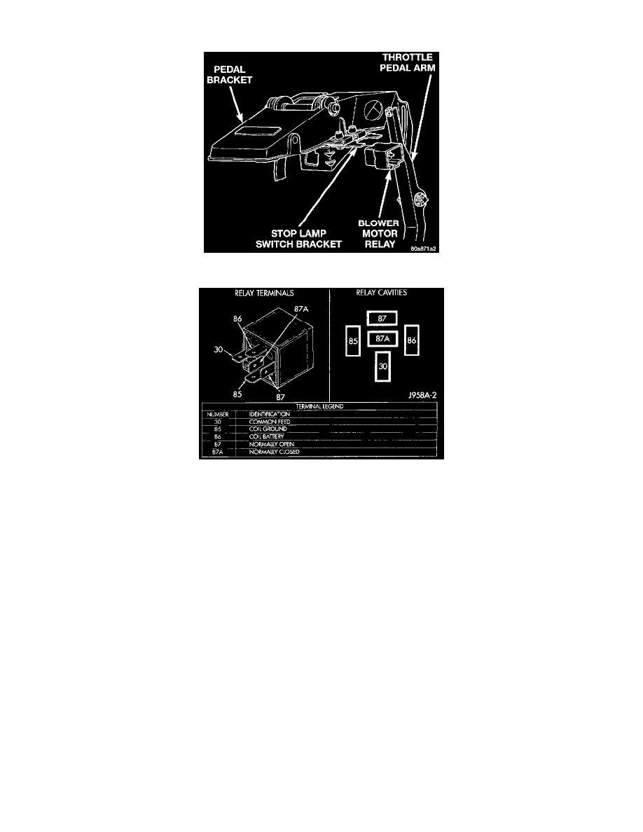
Fig 39 Blower Motor Relay Removal/Installation
Blower Motor Relay
OPERATION
The blower motor relay is a International Standards Organization (ISO)-type relay. The relay is a electromechanical device that switches battery
current from a fuse in the fuse block module to the blower motor, whenever the ignition switch is in the On position. This arrangement reduces the
amount of battery current that must flow through the ignition switch.
The relay is energized when the relay coil is provided a voltage signal by the ignition switch. When the relay is de-energized, the blower motor
receives no battery feed.
The relay is located in the passenger compartment on the stop lamp switch bracket. The stop lamp switch bracket is secured to the inboard side of
the pedal support bracket under the driver side of the instrument panel. The relay case includes a molded-in plastic slot that snaps over the
blade-type relay mount on the stop lamp switch bracket. The relay cannot be repaired and, if faulty or damaged, it must be replaced.
CIRCUIT OPERATION
Circuit C1 from fuse 2 in the Fuse Block supplies voltage to the contact side of the blower motor relay
When the ignition switch is in the RUN position it connects Circuit A2 from fuse 2 in the Power Distribution Center (PDC) to Circuit A22. Circuit
A22 connects to the coil side of the blower motor relay
Circuit C1 connects to Circuit C11 through the blower motor relay contacts and supplies voltage to the blower motor.
Circuit Z3 provides the ground path for the blower motor relay.