
2500 4x2 Pickup V10-488 8.0L Magnum (1996)
Malfunction Indicator Lamp: Description and Operation
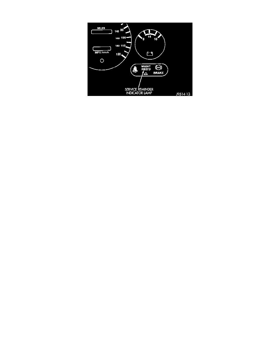
Fig. 1 SRI Lamp Location
DESCRIPTION
The service reminder indicator (SRI) lamp is used with Heavy Duty Cycle (HDC) engines only. The lamp is displayed on the instrument panel as
the MAINT REQ'D lamp. The SRI system is incorporated into the powertrain control module (PCM).
OPERATION
As a functional test, the Malfunction Indicator Lamp (MIL) (check engine) illuminates at key-on before engine cranking. Whenever the
Powertrain Control Module (PCM) sets a Diagnostic Trouble Code (DTC) that affects vehicle emissions, it illuminates the MIL. If a problem is
detected, the PCM sends a message to the instrument cluster to illuminate the lamp. The PCM illuminates the MIL only for DTC's that affect
vehicle emissions. There are some monitors that may take two consecutive trips, with a detected fault, before the MIL is illuminated. The MIL
stays on continuously when the PCM has entered a Limp-In mode or identified a failed emission component.
Also, the MIL either flashes or illuminates continuously when the PCM detects active engine misfire. The PCM may reset (turn off) the MIL when
one of the following occur:
^
PCM does not detect the malfunction for 3 consecutive trips (except misfire and Fuel system Monitors).
^
PCM does not detect a malfunction while performing three successive engine misfire or fuel system tests. The PCM performs these tests while
the engine is operating within +/- 375 RPM of and within 10 % of the load of the operating condition at which the malfunction was first
detected.
NOTE: Failure to perform the part replacement or required maintenance and only reset the SRI lamp may be a violation of federal law. Only after
performing the part replacement or required maintenance should the SRI lamp be reset.
CIRCUIT OPERATION
The Powertrain Control Module (PCM) provides ground for the instrument cluster malfunction indicator lamp on circuit G3. Circuit G3 connects
to cavity C17 of the PCM. Circuit F14 provides voltage for the lamp. The MIL displays the message CHECK ENGINE when illuminated.