
2500 4x4 Pickup L6-359 5.9L DSL Turbo (1995)
Malfunction Indicator Lamp: Description and Operation
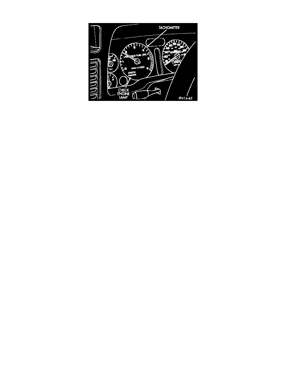
Check Engine Lamp
OPERATION
The Malfunction Indicator Lamp (formerly referred to as the check engine lamp) illuminates on the instrument panel each time the ignition key is
turned on. It will stay on for about three seconds as a bulb test.
If the Powertrain Control Module (PCM) receives an incorrect signal, or no signal from certain sensors or components, the lamp is turned ON.
This is a warning that the PCM has recorded a system or sensor malfunction. It signals an immediate need for service.
The lamp can also be used to display a diagnostic trouble code (DTC). Cycle the ignition switch On-Off-On-Off-On within three seconds and any
codes stored in the PCM memory will be displayed. This is done in a series of flashes representing digits.
The Powertrain Control Module (PCM) provides ground for the instrument cluster malfunction indicator lamp on circuit G3. Circuit G3 connects
to cavity 32 of the PCM. Circuit F14 provides voltage for the lamp. The MIL displays the message CHECK ENGINE when illuminated.