
2500 4x4 Pickup V8-360 5.9L VIN 5 Magnum (1994)
Charge Temperature Sensor: Testing and Inspection
NOTE:
To perform a complete test of Intake Air Temperature sensor and its circuitry, refer to appropriate Diagnostic Chart. To test the sensor only, refer
to the following:
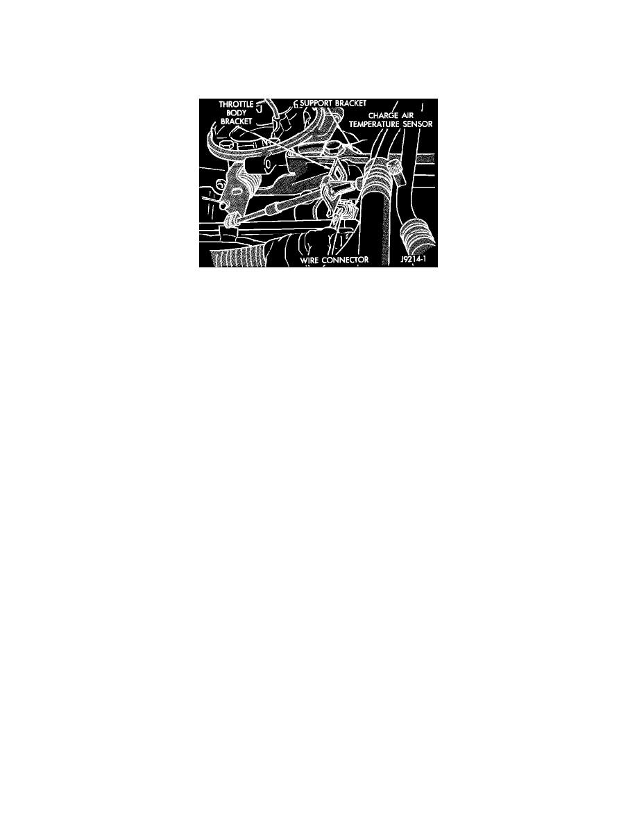
Charge Air Temperature Sensor And Connector
1.
Disconnect the wire harness connector from the sensor.
2.
Test the resistance of the sensor with an input impedance (digital) volt-ohmmeter. The resistance (as measured across the sensor terminals) should
be less than 1340 ohms with the engine warm. Refer to the Coolant Temperature sensor/Charge Air Temperature sensor resistance chart. Replace
the sensor if it is not within the range of resistance specified in the chart.
3.
Test the resistance of the wire harness. Do this between the Powertrain Control Module wire harness connector terminal 21, and the sensor
connector terminal. Also check between terminal 4 to the sensor connector terminal. Repair the wire harness as necessary if the resistance is
greater than 1 ohm.
...............................................................................................................................................................................................................................................
TEMPERATURE
RESISTANCE (OHMS)
°C
°F
MIN
MAX
...............................................................................................................................................................................................................................................
-40
-4O
291,490
381,710
-20
-4
85,850
108,390
-10
14
49,250
61,430
0
32
29,330
35,990
10
50
17,990
21,810
20
68
11,370
13,610
25
77
9,120
10,880
30
86
7,370
8,750
40
104
4,900
5,750
50
122
3,330
3,880
60
14O
2,310
2,670
70
158
1,630
1,870