
3500 4x2 Pickup L6-359 5.9L DSL Turbo (1994)
from front of engine) 1/4 turn or until you see the dial indicator reading stop dropping. This is the inner base circle of the injection pump cam.
Zero the indicator and note the reading on the small inner dial (Figure 10).
CAUTION:
BE SURE THE TIMING PIN IS DISENGAGED BEFORE ROTATING THE ENGINE TO AVOID DAMAGE TO THE TIMING PIN.
13.
Rotate the engine clockwise slowly to TDC. Note the pump lift setting on the dial indicator (Figure 10).
IMPORTANT:
All 1994 Cummins Diesel Engine vehicles equipped with a manual transmission should be set to 12.5 degrees engine timing. All automatic
transmission equipped vehicles should be set to the timing specified on the engine data plate. Refer to the engine "Timing-TDC" listed on the Engine
Data Plate and compare it to the Pump Lift Setting/Engine Timing listed.
Adjust Injection Pump Timing:
14.
If a change in injection timing is required, remove the oil filler tube and adapter elbow from the front of the gear housing.
15.
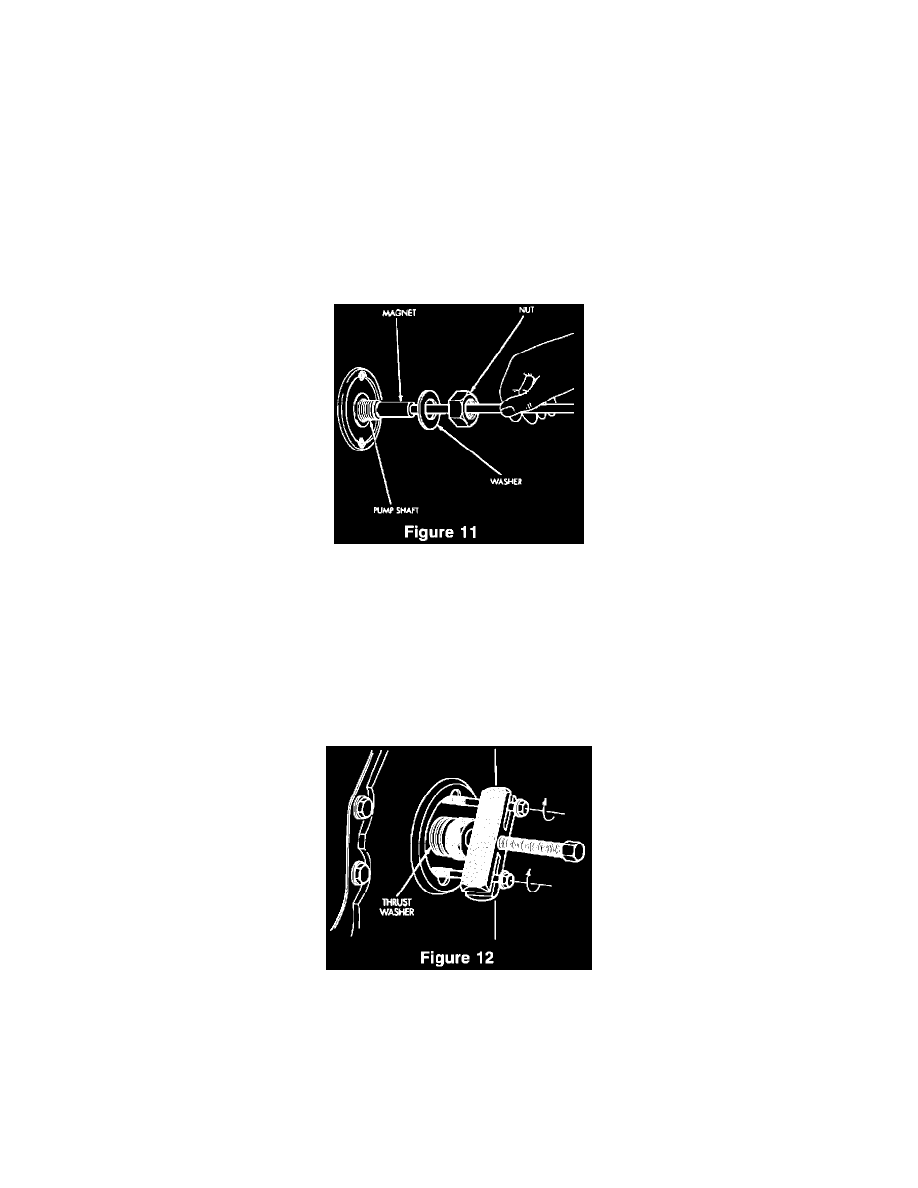
Place a magnet on the end of the shaft and remove the shaft nut (use the barring tool to keep the engine from rotating), (Figure 11). Install bearing
and thrust washer, Miller P/N 6862, and re-install the shaft nut.
CAUTION:
IF THE INPUT SHAFT NUT AND WASHER ARE REMOVED, WITHOUT USING A MAGNET, THE NUT OR WASHER MAY DROP
DOWN INSIDE OF THE TIMING GEAR COVER, REQUIRING SIGNIFICANT DISASSEMBLY OF THE ENGINE IN ORDER TO RECOVER
THEM.
16.
Slowly rotate the engine clockwise until reaching the required lift setting on the dial indicator. The injection pump should rotate with the engine
since the pump gear is still locked to the injection pump shaft.
17.
With the injection pump at the correct plunger lift setting, use gear puller, Miller P/N L-4407A, to pull the injection pump gear off the taper of the
injection pump input shaft. Leave the gear puller installed (Figure 12).