
3500 4x2 Pickup L6-359 5.9L DSL Turbo (1994)
3.
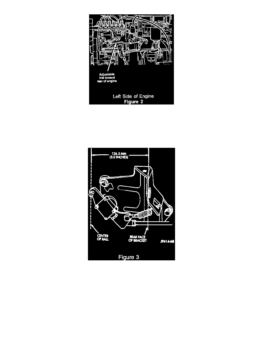
Install throttle control rod assembly, P/N 4773482, to the lever, P/N 4773483. Install the adjustable link end of the rod on the lever (Figure 2).
Note:
The throttle control rod comes pre-assembled and should measure 348.1 mm (center of ball to center of ball). Adjust the rod length as required.
4.
Install the new throttle control lever/rod to the engine and secure with the two screws removed in step 2. Install the throttle return spring and
complete the installation of the throttle control rod.
5.
Measure the distance from the rear face of the bracket to center of ball. Lengthen or shorten the throttle control rod to provide a dimension of
126.5 +/- 1.0 mm (Figure 3).
6.
Adjust the throttle position sensor. This can be accomplished by using the volt meter feature on the DRB II (Scan Tool) or using a digital volt
meter.
A)
Attach a paper clip into the center terminal of the TPS electrical connector. Do not remove the connector from the TPS.
B)
Attach the positive lead of the voltmeter to this paper clip and the negative lead to a good ground.
C)
Turn the ignition switch to the ON position. Do not start the engine.
D)
Turn the throttle rod adjusting link until a closed throttle voltage of 1.0 VDC (+/- .2 VDC). The voltage at the wide open throttle position