
3500 4x4 Pickup L6-359 5.9L DSL Turbo (1996)
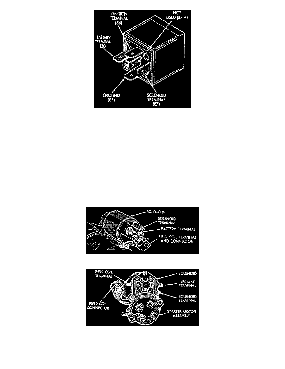
Fig 3 Starter Relay Terminal Identification
1. Remove starter relay from relay center.
2. Check resistance between ground and ignition terminals. Resistance value between ground and ignition terminals should be 70-80 ohms for
resistor relays and 81-91 ohms for diode relays.
3. Apply battery voltage to relay ignition terminal and connect ground terminal to ground. Continuity should exist between battery and solenoid
terminals. If continuity does not exist, replace relay.
Clutch Pedal Switch
The clutch pedal switch is a normally open type switch.
1. Locate and disconnect clutch pedal switch connector.
2. Using a suitable continuity tester, check circuit through switch with pedal released, there should be no continuity.
3. With continuity tester still attached, push clutch pedal to floor, tester should show full continuity.
4. Tester should not show continuity until pedal is fully depressed, replace switch if it fails any test.
Starter Solenoid Bench Test
Fig 6 Bosch Starter Solenoid Terminal Identification
Fig 7 Nippondenso Starter Solenoid Terminal Identification
1. Remove starter assembly from vehicle.
2. Disconnect field coil wire from field coil terminal.
3. Check for continuity between solenoid terminal and field coil terminal. Continuity should exist.