
3500 4x4 Pickup V8-360 5.9L Magnum (1996)
NOTE:
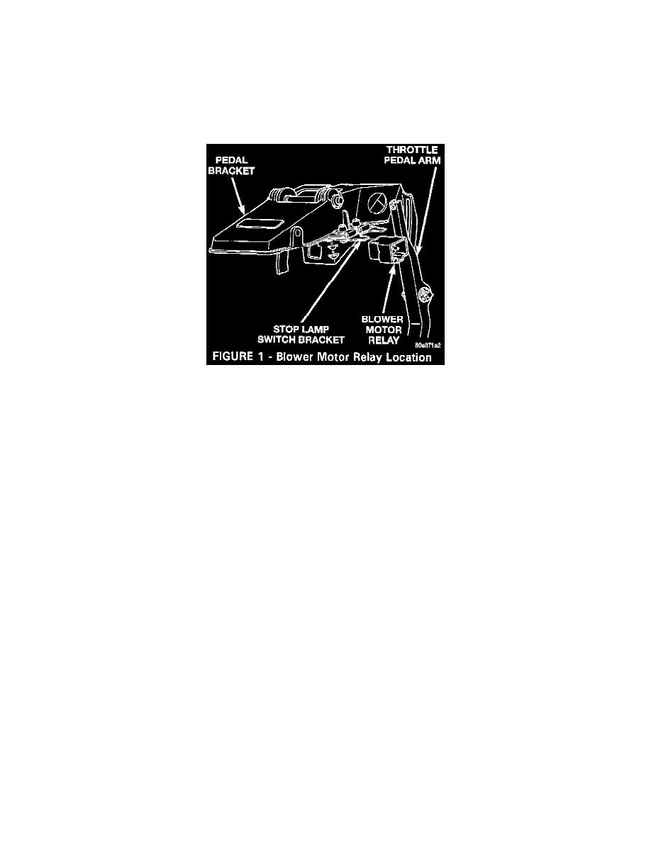
RAM TRUCKS THAT HAVE THE IGNITION SERVICE KIT INSTALLED CAN BE IDENTIFIED BY VERIFYING THAT THE BLOWER
FAN RELAY IS ATTACHED TO THE STOP LAMP SWITCH BRACKET (FIGURE 1) AND THAT THE COLOR CODE OF THE WIRING
MATCHES THAT OF THE WIRING DIAGRAM (FIGURE 2).
CAUTION:
SOME RAM TRUCKS ARE EQUIPPED WITH FOG LAMPS AND THE FOG LAMP RELAY, WHICH IS ALSO ATTACHED TO THE STOP
LAMP SWITCH BRACKET, MAY BE CONFUSED WITH THE BLOWER FAN RELAY.
The blower motor relay provides battery voltage to the blower motor when the ignition switch is turned to the RUN position. The relay is located in the
passenger compartment and is attached to the stop lamp switch bracket (Figure 1).
The 1996 Ram Truck Service Manual (Publication No. 81-370-6108), page 8W-42-4, provides the wiring diagram that supports vehicles built before
March 15,1996. The following wiring diagram (Figure 2) takes place of the fuse circuit (Fuse F2) and the blower motor wiring diagram for vehicles built
after March 15,1996. This diagram can also supplement 1994 Ram Truck Service Manual (Publication No. 81-370-4108), pages 8W-146 and 8W-147
and the 1995 Ram Truck Service Manual (Publication No. 81-370-5108), page 8W-42-4, for vehicles that have ignition switch service kit P/N 4874996.
The blower motor relay is installed in series between the ignition switch and the blower motor. When the ignition switch is in the RUN position, battery
voltage is provided to the relay terminal 86 (relay coil) from ignition switch terminal 5 (A22 12BK/OR circuit). Terminal 85 of the relay (relay coil) is
routed to a ground. Refer to the appropriate Service Manual for ground splices and locations (G202 for 1996, G203 for 1995, and Z3-1 splice for 1994).
Battery voltage is supplied to terminal 30 of the relay (moving contacts of relay - C1 12DG) from the Power Distribution Center Fuse 2 (A2 12PK/BK)
through Fuse F2 in the Fuse Block. Terminal 87 of the relay (stationary contact) is connected to the blower motor (C11 12DG).
With the ignition switch in the RUN position, the blower motor relay coil is energized. With the relay energized, the movable contact of the relay is
connected to the stationary contact providing battery voltage to the blower motor.
SYMPTOM/CONDITIONS:
Inoperative blower motor can be caused by any of the following components or circuits:
^
Faulty Fuse
^
Faulty Blower Motor Relay
^
Faulty Blower Motor Battery Feed Circuit
^
Faulty Blower Motor Ground Circuit
^
Faulty Blower Motor Resistor
^
Faulty Blower Motor Switch
^
Faulty Heater-A/C Mode Control Switch