
600 L4-135 2.2L SOHC (1983)
Constant Velocity Joint Boot: Service and Repair
Inner CV Joint Service
Assembly
1. On all models, slide small end of boot over shaft. On Tubular type shafts, align boot lip with mark on shaft outer diameter. On solid type shafts,
position small end of boot in groove on shaft.
2. Place rubber clamp over groove on boot.
3. Install tripod on shaft with non-chamfered face of tripod body facing shaft retainer groove.
4. Lock tripod assembly on shaft by installing retaining ring in shaft groove.
5. Distribute two packets of grease provided with boot and clamp kit into boot assembly on G.K.N. units, one packet on A.C.I. units, 2-3 packet on
CITROEN units or 1-2 packet on S.S.G. units.
6. On 1982---83 models with 4-105 engine and manual transaxle, install joint housing over tripod, then position large end of boot in groove in
housing. Add two additional packets of grease after boot has been secured to housing.
7. On early 1982 models less 4-105 engine with manual transaxle, distribute one packet of grease in housing before positioning housing over tripod.
On CITROEN units, reform retainer ring. On all units, secure boot to housing with boot clamp.
8. On late 1982 and 1983---87 models less 4-105 engine and manual transaxle, distribute remaining grease supplied into housing. Position spring,
with spring cup attached to exposed end, into spring pocket. Place a small amount of grease on spring cup, then position housing over tripod. On
CITROEN units, reform or replace retainer ring. On G.K.N. units, bend retaining tabs. On 1984 A.C.I. units, align rollers with retaining tabs and
housing tracks and pop one roller at a time through retaining tabs. On 1985---87 A.C.I. units, slide tripod onto housing. On 1986---87 S.S.G. units,
slip tripod into housing and install tripod wire retaining ring into position, ensuring retaining ring retains tripod in housing. Care must be taken to
ensure proper spring positioning. The spring must remain centered in housing spring pocket when tripod is installed and seated in spring cup. Do
not bend retaining tabs back to original position at this time, tripod must be engaged in housing when driveshaft is installed. On all units, position
boot over boot groove in housing, then install clamp. When installing housing, check to ensure that spring remains in pocket and centered in
housing. Also ensure that spring cup contacts spherical end of connecting shaft.
Disassembly
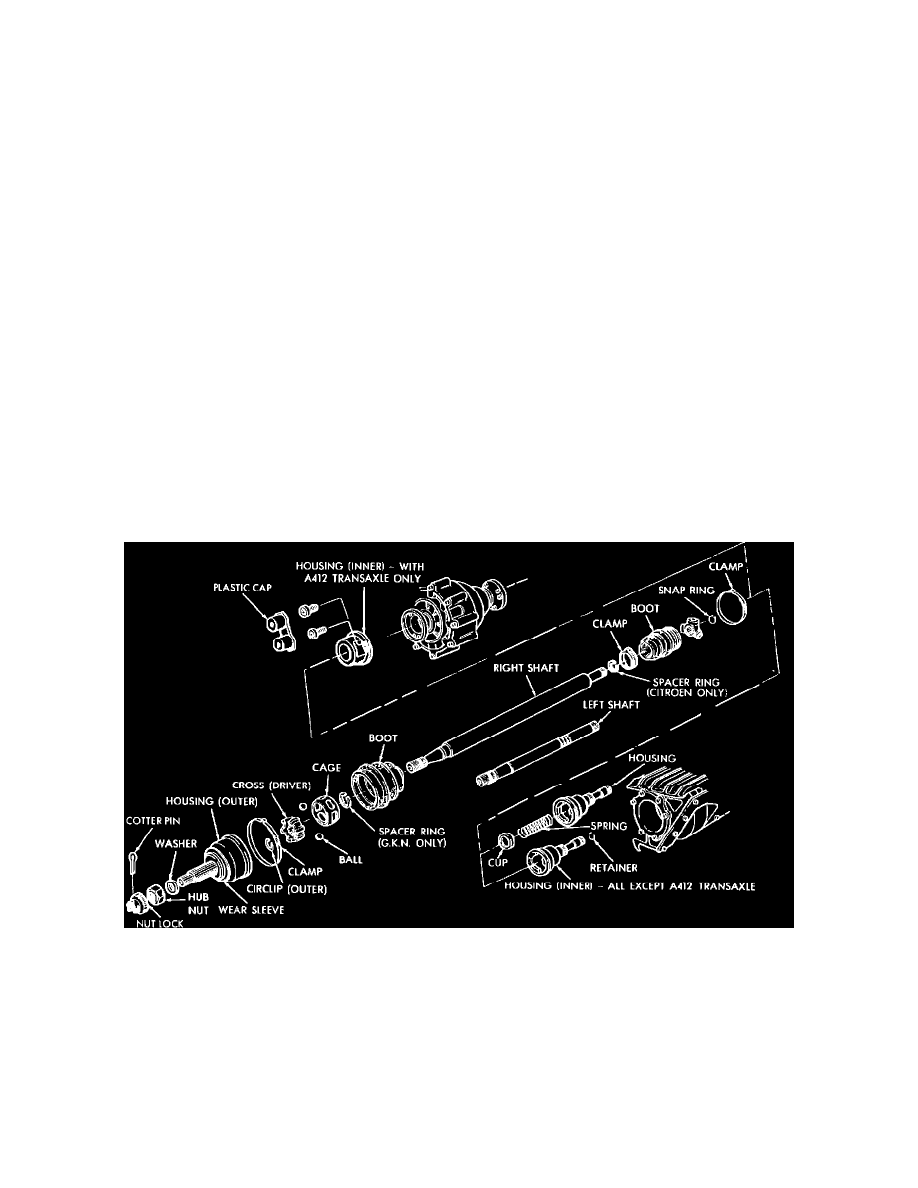
Fig. 17 Driveshaft components. 1982---83 (1984---87 similar)
1. Remove clamp and boot from joint and discard.