
600 L4-135 2.2L SOHC Turbo (1985)
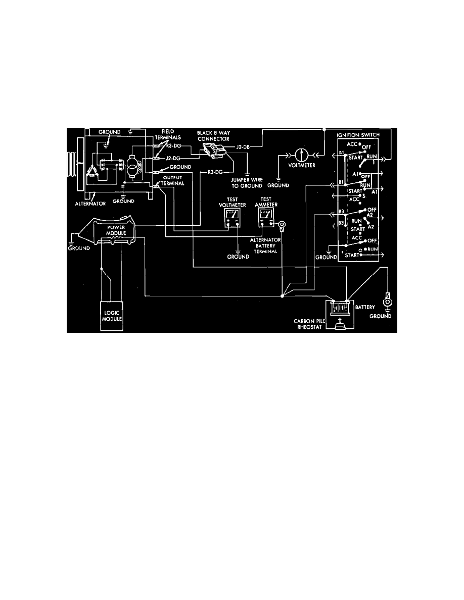
Fig. 8 Current output test. 1984---87 exc. units w/regulator in engine electronics
When testing alternators except 100 and 114 amp units, use a 0---100 amp ammeter. When testing 100 and 114 amp alternators, use a 0---150
amp ammeter.
EXC. UNITS W/REGULATOR IN-ENGINE ELECTRONICS
1.
Disconnect battery ground cable, complete test connections as shown and start engine and operate at idle. Immediately after starting, reduce engine
speed to idle.
2.
Adjust the carbon pile and engine speed in increments until a speed of 1250 RPM and 15 volts are obtained on all units except 100 and 114 amp
alternators. On 100 and 114 amp alternators, obtain engine speed of 900 RPM and 13 volts. While increasing speed, do not allow voltage to
exceed 16 volts.
3.
Check ammeter reading. Output current should be within specifications.
Fig. 9 Current output test. 1985---88 units w/regulator in engine electronics
UNITS W/REGULATOR IN ENGINE ELECTRONICS
1.
Disconnect battery ground cable and "Bat" lead from alternator output terminal.
2.
Complete test connections as shown.
3.
Remove air hose between power module and air cleaner, then the wiring harness electrical connector.
4.
Connect a suitable jumper wire from wiring harness connector green wire terminal to ground. Do not connect blue J2 lead of wiring electrical
connector to ground.
5.
Connect battery ground cable, then start engine and operate at idle.
6.
Adjust carbon pile rheostat and engine speed to obtain 15 volts at 1250 RPM. While increasing engine speed, do not allow voltage to exceed 16
volts.
7.
If ammeter reading is not approximately that of alternator rating, repair or replace alternator.
Bench Tests
To remove the alternator, disconnect the battery ground cable and the leads at the alternator. Then unfasten and remove the alternator from the vehicle.
FIELD COIL DRAW
1.
Place alternator on an insulated surface.
2.
On all units, connect a jumper wire between one alternator field terminal and the negative terminal of a fully charged battery.
3.
Connect test ammeter positive lead to the other alternator field terminal and the ammeter negative lead to the positive battery terminal.
4.
On 1982---83 units except 100 and 114 amp, connect a jumper wire between alternator end shield and negative terminal of battery.
5.
On all units, slowly rotate rotor by hand and note ammeter reading. On units except 100 and 114 amp, field current at 12 volts should be 4.5 to 6.5
amps (1984---88, 2.5---5.0 amps). On 100 and 114 amp units, field current should be 4.75 to 6.0 amps.
6.
A low rotor coil draw is an indication of high resistance in the field coil circuit (brushes, slip rings or rotor coil). A high rotor coil draw indicates
shorted rotor coil or grounded rotor. No reading indicates an open rotor or defective brushes.