
Avenger L4-2.4L (2009)
Brake Master Cylinder: Description and Operation
Brake Master Cylinder - Description
DESCRIPTION
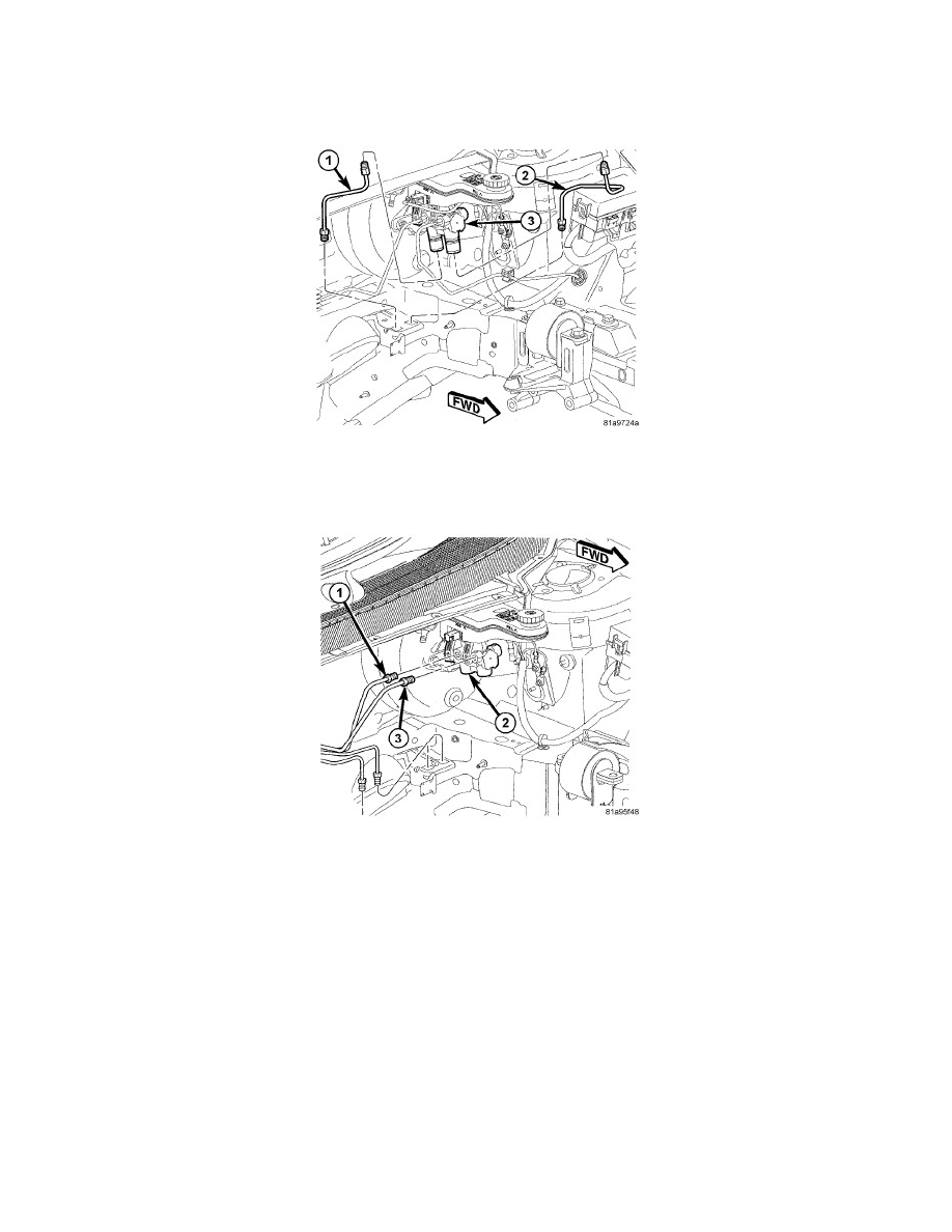
The non-ABS master cylinder (3) is a four-outlet design (one for each wheel brake). There are two ports at each piston. One feeds a front wheel brake
while the other feeds the opposite side rear wheel brake. The rear wheel brake ports are drilled and threaded to accept screw-in proportioning valves.
Both valves are threaded into the bottom of the master cylinder housing.
All ABS master cylinders (2) are a two-outlet design and the brake tubes from these primary and secondary outlet ports lead directly to the Integrated
Control Unit (ICU) before going to each wheel brake.
All master cylinders mount to the power brake booster in the same manner.
The master cylinder body is an anodized aluminum casting. It has a machined bore to accept the master cylinder pistons and also has threaded ports with
seats for hydraulic brake tube connections.
The master cylinder has the brake fluid reservoir mounted on top of it which gravity feeds brake fluid to the master cylinder when it is required. On
manual transmission model vehicles the brake fluid reservoir also feeds the clutch hydraulic circuit. The reservoir is made of see-through plastic and it
houses the brake fluid level switch. A removable brake fluid level switch is mounted in the right side.