
Avenger L4-2.4L (2009)
Engine Control Module: Testing and Inspection
CHECKING THE PCM POWER AND GROUND CIRCUITS (NGC)
For a complete wiring diagram, refer to the wiring information See: Diagrams/Electrical Diagrams.
1. PCM WIRING OR CONNECTORS
1. Turn the ignition off.
2. Using the wiring diagram/schematic as a guide, inspect the wiring and each connector at the PCM.
3. Look for any chafed, pierced, pinched, or partially broken wires.
4. Look for broken, bent, pushed out or corroded terminals.
Were any problems found?
Yes
-
Repair as necessary.
-
Perform the PCM VERIFICATION TEST. See: Powertrain Management/Computers and Control Systems/Testing and Inspection/Diagnostic
Trouble Code Tests and Associated Procedures/Verification Tests/PCM Verification Test.
No
-
Go To 2
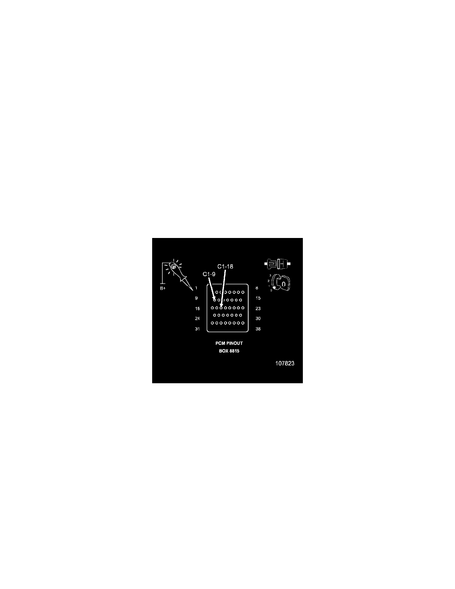
2. CHECKING THE PCM GROUND CIRCUITS
1. Turn the ignition off.
CAUTION: Do not probe the PCM harness connectors. Probing the PCM harness connectors will damage the PCM terminals resulting in
poor terminal to pin connection. Install PCM Pinout Box 8815 to perform diagnosis.
2. Using a 12-volt test light connected to 12 volts, check the PCM ground circuits.
3. Wiggle test each circuit during the test to check for an intermittent open in the circuit.
NOTE: The test light should be illuminated and bright. Compare the brightness to that of a direct connection to the battery.
Is the test light illuminated and bright?
Yes
-
Go To 3
No
-
Repair the PCM ground circuit(s) for an open circuit or high resistance.
-
Perform the PCM VERIFICATION TEST. See: Powertrain Management/Computers and Control Systems/Testing and Inspection/Diagnostic
Trouble Code Tests and Associated Procedures/Verification Tests/PCM Verification Test.