
B350 1 Ton Van V8-360 5.9L VIN W 4-bbl (1988)
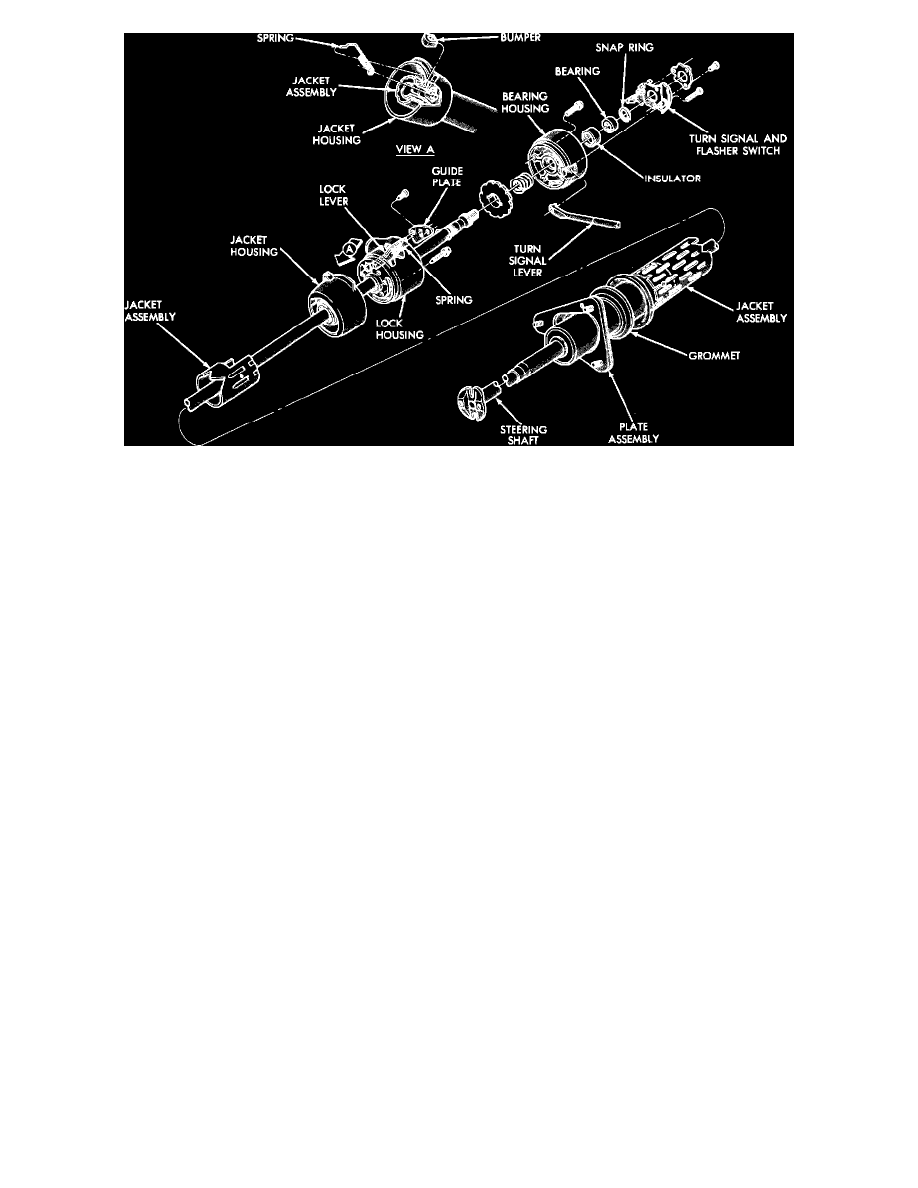
Fig. 11 Non-tilt wheel steering column exploded view (floor shift man. trans.)
SHIFT LEVER, TURN SIGNAL SWITCH & LAMP ASSEMBLY
1.
Pry out wiring trough retainers and lift off wiring trough.
2.
Using a suitable punch, drive out shift lever roll pin. Use a deep socket to accept the roll pin as it is driven out.
3.
Place steering column in a vise by securing it at the bracket.
4.
Remove turn signal switch and upper bearing retaining screws, then remove retainer and lift switch up and out of the way.
5.
Remove retaining screw and lift off ignition key lamp assembly up and out of the way.
STEERING SHAFT
1.
Remove snap ring from upper end of steering shaft.
2.
Remove three screws retaining bearing housing to lock housing. These screws must be removed before steering shaft is removed.
3.
Remove bearing housing from shaft, and then the coil spring.
4.
Remove lock plate from shaft, then remove shaft through lower end of column.
LOCK HOUSING
1.
If equipped with shift indicator dial, remove pointer screw and position pointer aside.
2.
If equipped, remove screw and lift out buzzer switch.
3.
Remove two retaining screws and lock lever guide plate to expose the lock cylinder release hole.
4.
Place cylinder in Lock position and remove key. Insert a small screwdriver into lock cylinder release hole and push in to release spring loaded lock
retainer, while pulling lock cylinder out of the housing.
5.
Remove the three retaining screws and ignition switch assembly.
6.
Grasp lock lever and spring assembly and pull straight out of housing.
7.
Remove the four lock housing to column jacket hex retaining screws and remove housing from jacket.
SHIFT TUBE
1.
On Ramcharger and D/W-100-350 series models with automatic transmission, loosen shift tube setscrew in shift housing and remove shift
tube through lower end of jacket.
2.
On Van and Wagon models with automatic transmission, remove indicator bracket and then the shift tube through the lower end of the jacket.
3.
On Van and Wagon models with manual transmission, remove the three bearing support screws at lower end of jacket and the three adjustable
bushing screws from cam slots in jacket, then remove shift tube and lever assembly through lower end of jacket.
4.
On all models, remove floor plate and grommet from jacket.