B350 1 Ton Van V8-5.9L VIN Z (1992)

become disengaged from grooves in cylinder head and housing. Also, the center spacer may separate from center race and jam in the housing, in
turn damaging the spacer and/or housing when removing the power train.
ASSEMBLE
1.
With steering gear housing fastened in holding fixture, lubricate power train housing bore with fluid and install power train assembly. Face piston
teeth to the right and valve lever hole in center race and spacer in Up position. Ensure cylinder head is bottomed against housing shoulder.
2.
With valve lever hole in center bearing race and spacer aligned with valve level hole in gear housing, install valve lever (double bearing end first)
into center bearing race and spacer, ensuring valve lever slots are parallel to worm shaft. It may be necessary to gently tap end of valve lever to
seat lower pivot point in center race.
3.
Install housing head tang washer, indexing with groove in housing, and steering column support nut, and torque nut to 150-200 ft. lbs. Ensure
valve lever remains centered in housing hole by rotating worm shaft until piston bottoms in both directions and observe valve lever action. The
valve lever must be in center of hole and return to the center position when worm shaft torque is relieved.
4.
Install valve lever spring (small end first), position power piston at center of travel and install sector shaft and cover assembly, indexing sector
teeth with piston rack teeth. Ensure sector shaft cover O-ring is installed properly.
5.
Install and torque cover nut to 110-200 ft. lbs.
6.
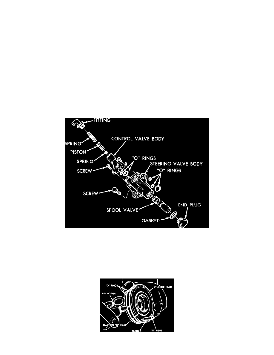
Install valve body onto housing with valve lever entering hole in valve spool. Ensure O-rings are installed properly, then install and torque valve
retaining screws to 7 ft. lbs.
Disassembly
Fig. 4 Exploded view of Chrysler Constant Control power steering gear
1.
Place powertrain vertically in a suitable soft jawed vise to prevent damage to piston assembly. To retain 33 worm bearing needle roller bearing
during housing head removal, use arbor No. C-3929 or equivalent.
2.
Raise housing head until worm shaft oil seal clears top of worm shaft, then position tool No. C-3929 on top of worm shaft and into seal. Raise
housing head until arbor is positioned in bearing, then remove housing head and arbor. If bearings become dislodged during head removal,
retain in housing head using a suitable grease for installation. If necessary to replace worm shaft oil seal, perform operation with housing
head installed in gear housing.
Fig. 5 Reaction seal removal
