
B350 1 Ton Van V8-5.9L VIN Z (1992)
3.
Remove large O-ring from housing head, then the reaction seal from groove in housing head face by forcing compressed air into ferrule chamber.
4.
Remove reaction spring, reaction ring, worm balancing ring and spacer, then retain worm shaft rotation and remove nut from knurled section.
5.
Remove thin upper bearing race, then the thrust bearing.
6.
Remove center bearing race, then the lower thrust bearing and thick race.
7.
Remove lower reaction ring and spring, then the cylinder head assembly.
8.
Remove two cylinder head outer groove O-rings, then the reaction O-ring from groove in face of cylinder head by forcing compressed air into oil
hole located between the two O-ring grooves. Remove snap ring and seal.
FIg. 6 Cylinder head oil seal ring removal
9.
Remove snap ring, sleeve and rectangular oil seal ring from cylinder head counterbore.
10.
Ensure torque required to rotate worm shaft throughout its full travel in or out of piston is 1.0-1.5 inch lbs., with optimal being 1.25 inch lbs. The
worm and piston assembly are serviced as a complete unit and should not be disassembled.
Assembly
1. Seat piston ring in its groove by pressing down on piston, opening the ends for proper locking action.
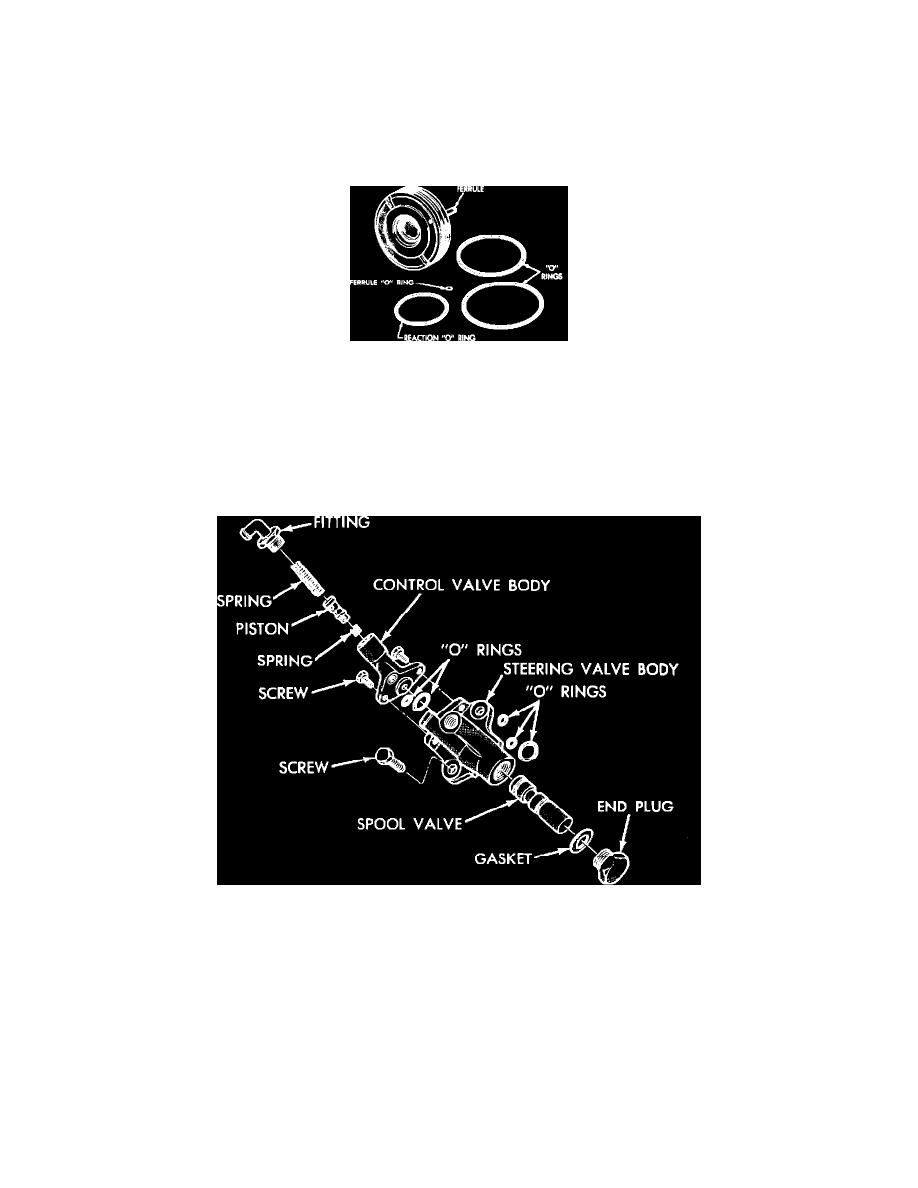
Fig. 4 Exploded view of Chrysler Constant Control power steering gear
2. Vertically position piston assembly (worm shaft side up) in a suitable soft jawed vise, then lubricate two large O-rings with a suitable lubricant.
Install O-rings into cylinder head grooves.
3. Install worm sleeve seal, sleeve and snap ring, if removed, then install lower reaction O-ring seal in cylinder head groove.
4. Slide cylinder head assembly ferrule side up on worm shaft, then inspect worm shaft seal ring to ensure gap is closed to avoid ring damage as
cylinder head contacts piston flange.
5. Lubricate the following parts with a suitable power steering fluid, then install in order as follows:
a. Thick lower thrust bearing race.
b. Lower thrust bearing.
c. Lower reaction spring, ensuring small hole is over ferrule.
d. Lower reaction ring with flange up so ring protrudes through reaction spring and contacts O-ring in cylinder head.
e. Center bearing race.
f.
Upper thrust bearing.