
Caliber L4-2.0L (2008)
CAUTION: When shifting the front crossmember, keep in mind that the front and rear engine mounts are attached to the front
crossmember and fore/aft crossmember and should be inspected following the crossmember shift to make sure they are properly aligned.
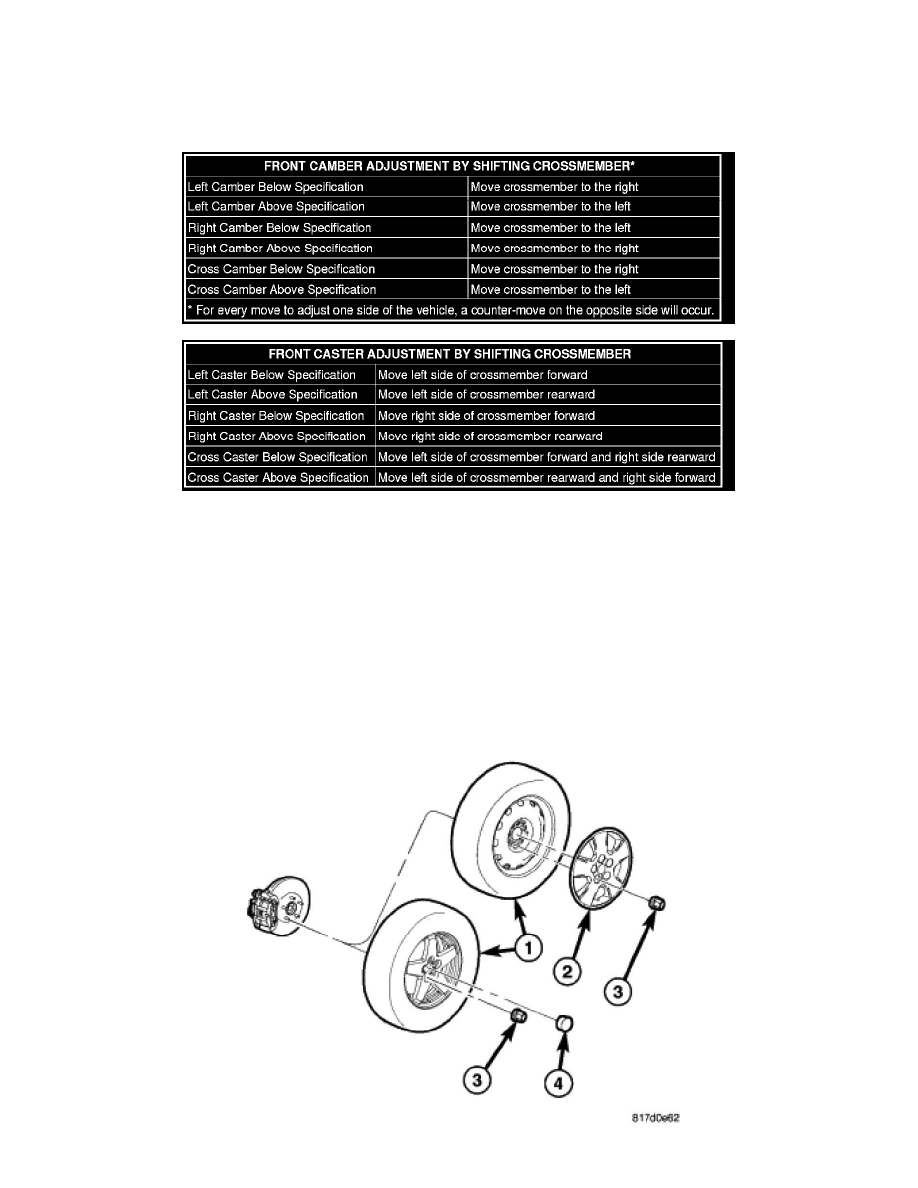
3. Shift front crossmember as necessary (See following tables) to bring camber or caster into specifications. When shifting crossmember, use care not
to move other angles (camber or caster) that are within specifications, out of specifications.
4. Tighten all previously loosened fasteners (bolts) securing the crossmember to the vehicle to specifications. See: Suspension/Cross-Member/Front
Cross-Member/Service and Repair
5. Jounce the rear, then front of the vehicle an equal amount of times.
6. Measure camber and caster. If camber and caster are within specifications, proceed to TOE. If camber cannot be brought into specifications,
perform the CAMBER ADJUSTMENT BOLT PACKAGE INSTALLATION below.
CAMBER ADJUSTMENT BOLT PACKAGE INSTALLATION
The camber adjustment bolt package contains new bolts and nuts for attaching the strut clevis bracket to the steering knuckle. The bolts contained in the
package are slightly undersize allowing for movement between the strut clevis bracket and the steering knuckle. The movement allowed by the undersize
bolts provide approximately two degrees of camber adjustment per side of the vehicle. To install and adjust the camber adjustment bolt package, follow
the procedure below.
7. Raise the vehicle until its tires are not supporting the weight of the vehicle. See: Wheels and Tires/Vehicle Lifting/Service and Repair