
Caravan V6-201 3.3L (1995)
4. Remove the insulation from the wires in the harness. Only remove enough insulation to solder in the new diode.
5. Install the new diode in the harness, making sure current flow is correct.
6. Solder the connection together using rosin core solder only. Do not use acid core solder.
7. Tape the diode to the harness using electrical tape, making sure the diode is completely sealed from the elements.
8. Re-connect the battery and test affected systems.
Fusible Link Replacement
CAUTION: Do not replace blown fusible links with a standard wire. Only use fusible type wire with hypalon insulation or damage to the electrical
system could occur. Also make sure correct gauge of wiring is used. Refer to the wiring diagrams for proper gauge and color.
When a fusible link blows it is important to find out what the problem is. They are placed in the electrical system for protection against shorts to ground.
Which can be caused by a component failure or various wiring failures. Do not just replace the fusible link to correct the problem.
When diagnosing a faulty fusible link it is important to check the wire carefully. In some instances the link may be blown and it will not show through
the insulation, the wire should be checked over its entire length for internal breaks.
1. Disconnect battery negative cable.
2. Cut out the blown portion of the fusible link.
3. Strip one inch of insulation from each end of the existing fusible link.
4. Place a piece of heat shrink tubing over one side of the fusible link. Make sure the tubing will be long enough to cover and seal the entire repair
area.
5. Cut a replacement piece of fusible link two inches longer than the piece removed.
6. Remove one inch of insulation from each end of the replacement fusible link.
Wire Repair
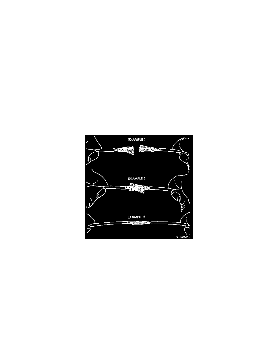
7. Spread the strands of wire apart on each of the exposed wires (Example 1).
8. Push the two ends of the wire together until the strands of wire are close to the insulation (Example 2).
9. Twist the wires together (Example 3).
10. Solder the wires together using rosin core type solder only. Do not use acid core type solder.
11. Center the heat shrink tubing over the joint and heat using a heat gun. Heat the joint until the tubing is tightly sealed and sealant comes out of both
ends of the tubing.
12. Secure the fusible link to the existing ones to prevent chafing or damage to the insulation.
13. Connect battery and test all affected systems.
Terminal Replacement
1. Disconnect the battery.
2. Disconnect the connector being repaired from its mating half/component.