
Caravan V6-201 3.3L (1995)
Camshaft Position Sensor: Description and Operation
Camshaft Sensor
PURPOSE
-
Sensor provides PCM with cylinder identification.
-
PCM uses sensor input to determine fuel injection sequence and ignition timing.
OPERATION
Sensor generates pulses as groups of notches on the camshaft sprocket pass underneath it.
-
When metal aligns with the sensor, voltage goes low (less than 0.3 volts).
-
When a notch aligns with the sensor, voltage spikes high (5.0 volts).
-
As a group of notches pass under the sensor, the voltage switches from low (metal) to high (notch) then back to low.
-
The number of notches determine the amount of pulses.
NOTE: If available, an oscilloscope can display the square wave patterns of each timing event.
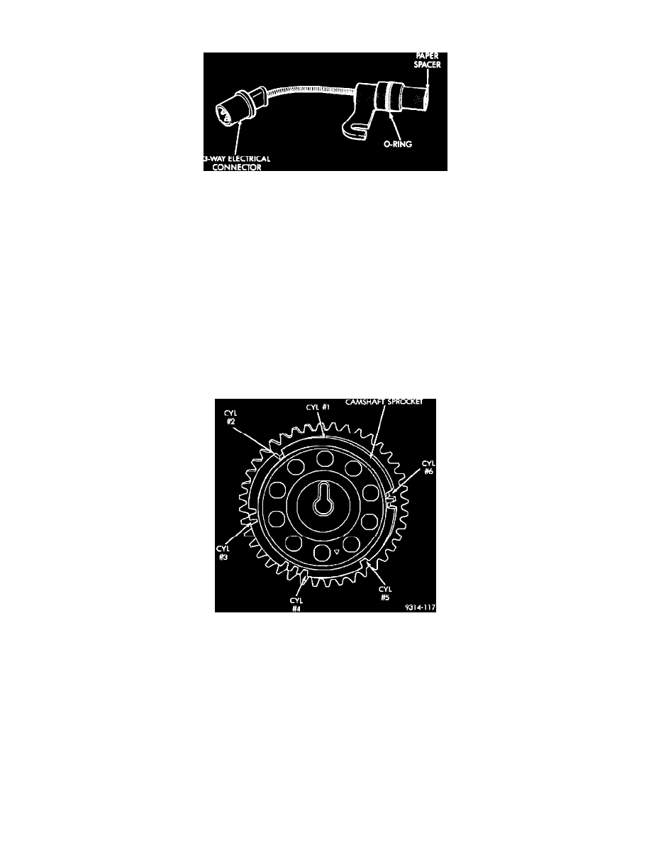
NOTE: The arrows and cylinder call outs on the following image represent which cylinder the flat spot and notches identify, they do not indicate Top
Dead Center (TDC) position.
Camshaft Sprocket
-
When the PCM receives two cam pulses followed by the long flat spot on the camshaft sprocket, it knows that the crankshaft timing marks for
cylinder # 1 are next (on driveplate).
-
When the PCM receives one camshaft pulse after the long flat spot on the sprocket, cylinder number # 2 crankshaft timing marks are next.
-
After 3 camshaft pulses, the PCM knows cylinder # 4 crankshaft timing marks follow.
-
One camshaft pulse after the three pulses indicates cylinder # 5.
-
The two camshaft pulses after cylinder 5 signals cylinder # 6.
-
The PCM can synchronize on cylinders 1 or 4.
NOTE: TDC does not occur when notches on the camshaft sprocket pass below the cylinder. TDC occurs after the camshaft pulse (or pulses) and after
the 4 crankshaft pulses associated with the particular cylinder.
NOTE: The distance between the sensor and camshaft sprocket is critical to system operation. Be sure paper spacer is attached to sensor face when
installing sensor. SEE Powertrain Management/Computers and Control Systems/Camshaft Position Sensor/Service and Repair.