
Caravan V6-3.3L VIN R (2003)
Seat Heater: Description and Operation
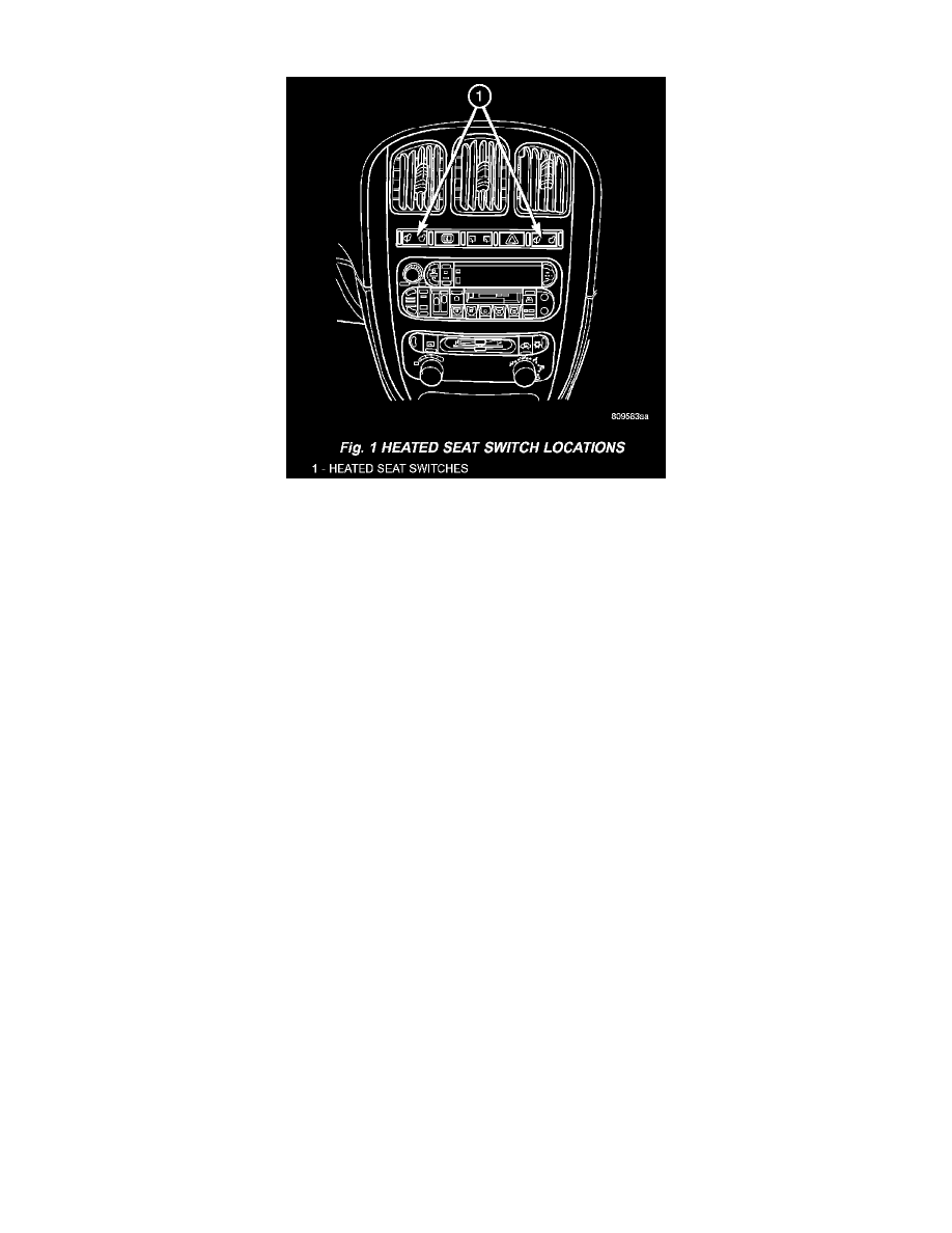
Fig.1 Heated Seat Switch Locations
HEATED SEAT SYSTEM
Vehicles with the heated seat option can be visually identified by the two separate heated seat switches located in the instrument panel center stack,
just above the radio. The heated seat system allows the front seat driver and passenger to select from two different levels of supplemental electrical
seat heating (HI/LO), or no seat heating to suit their individual comfort requirements. The heated seat system for this vehicle includes the
following major components, which are described in further detail later in this section:
-
Heated Seat Elements - Four heated seat elements are used per vehicle, two for each front seat. One heated seat element is integral to each
front seat trim cover, one in the seat back and one in the seat bottom (cushion). Service replacement heating elements are available, refer to
heated seat elements later in this section for additional information.
-
Heated Seat Modules - Two heated seat modules are used per vehicle. One module is mounted to each of the seat cushion pans, located under
the forward edge of each front seat. Refer to heated seat module in the electronic control modules section of the service manual for additional
information.
-
Heated Seat Sensors - Two heated seat sensors are used per vehicle, one for each front seat. The heated seat sensors are integral to each of the
heated seat bottoms (cushions).
-
Heated Seat Switch - Two heated seat switches are used per vehicle, one for the driver and one for the passenger side front seats. The switches
are mounted to in the instrument panel center stack. Refer to the description of the heated seat switch later in this section for additional
information.
Hard wired circuitry connects the heated seat system components to each other through the electrical system of the vehicle. These hard wired
circuits are integral to several wire harnesses, which are routed throughout the vehicle and retained by many different methods. These circuits may
be connected to each other, to the vehicle electrical system and to the heated seat system components through the use of a combination of soldered
splices and splice block connectors. Refer to Wiring for complete system wiring schematics. The wiring information also includes the proper wire
and connector repair procedures, further details on wire harness routing and retention, as well as pin-out and location views for the various wire
harness connectors, splices and grounds.
The heated seat system components operate on battery current received through a fuse in the Integrated Power Module (IPM) on a fused ignition
switch output (run-acc) circuit so that the system will only operate when the ignition switch is in the ON or Accessory positions. The heated seat
system will be turned OFF automatically whenever the ignition switch is turned to any position except ON or Accessory Also, the heated seat
system will not operate when the surface temperature of the seat cushion cover at either heated seat sensor is above the designed temperature set
points of the system. The heated seat system has a self-diagnostic capability. When certain failures are detected within the heated seat system, the
system will provide a visual indication of the failure by flashing the Light Emitting Diode (LED) indicator lamps located in the heated seat
switches. See the owner's manual in the vehicle glove box for more information on the features, use and operation of the heated seat system.