
Caravan FWD L4-2.4L VIN X (1997)
Brake Proportioning/Combination Valve: Service and Repair
NOTE: The actual proportioning valves of the proportioning valve assembly are not serviceable or replaceable. If a proportioning valve of the
proportioning valve assembly is not functioning properly, the fixed proportioning valve must be replaced as an assembly.
REMOVAL
1. Using a brake pedal depressor, move and lock the brake pedal to a position past its first 1 inch of travel. This will prevent brake fluid from
draining out of the master cylinder when the brake tubes are removed from the proportioning valve.
2. Raise vehicle on jackstands or centered on a hoist.
NOTE: Before removing the brake tubes from the proportioning valve, the proportioning valve and the brake tubes must be thoroughly cleaned.
This is required to prevent contamination from entering the proportioning valve or the brake tubes.
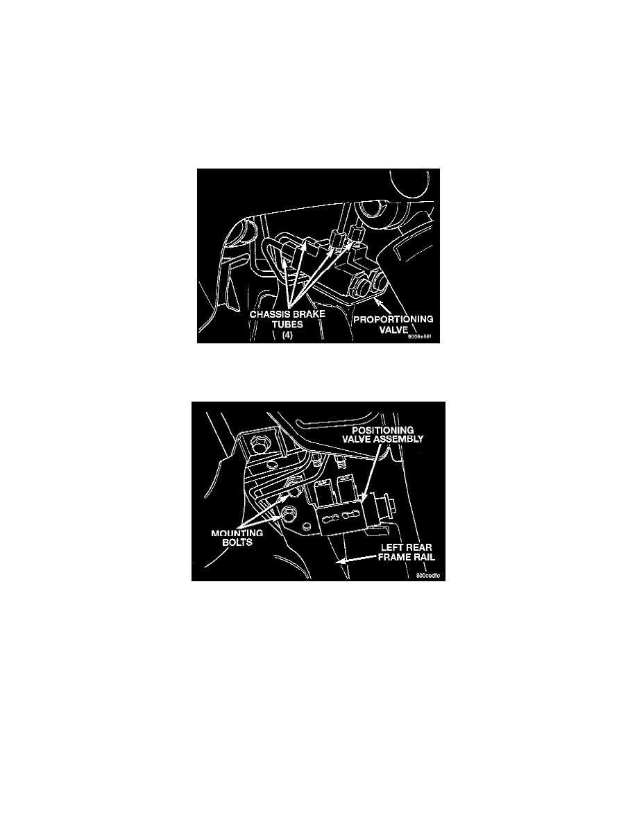
Chassis Brake Tubes At Proportioning Valve
3. Remove the 4 chassis brake lines from the inlet and outlet ports of the proportioning valve.
Proportioning Valve Attachment To Vehicle
4. Remove the bolts attaching the proportioning valve bracket to the frame rail of the vehicle. Remove the fixed proportioning valve assembly from
the vehicle.
NOTE: When mounting the original or a replacement proportioning valve on the frame rail of the vehicle install the mounting bolts in only the two
forward holes of the mounting bracket.
INSTALLATION
1. Install proportioning valve assembly on the frame rail of the vehicle. Install the proportioning valve assembly attaching bolts. Tighten the attaching
bolts to a torque of 14 Nm (125 inch lbs.).
2. Install the 4 chassis brake lines into the inlet and outlet ports of the proportioning valve assembly. Tighten all 4 line nuts to a torque of 16 Nm
(142 inch lbs.).
3. Bleed the brake system thoroughly enough to ensure that all air has been expelled from the hydraulic system. See: Brake Bleeding/Service and
Repair
4. Lower the vehicle to the ground.
5. Road test the vehicle to verify proper operation of the vehicle's brake system.