
Caravan FWD V6-3.3L VIN R (2001)
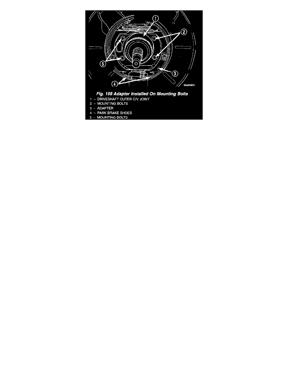
9. Position the adapter on the 4 mounting bolts installed in the rear axle.
10. Install the hub/bearing on the stub shaft of outer C/V joint and into the end of the axle.
11. In a progressive crisscross pattern, tighten the 4 hub/bearing mounting bolts until the hub/bearing is squarely seated against the axle. Then tighten
the hub/bearing mounting bolts to a torque of 129 Nm (95 ft. lbs.).
12. Install the wheel speed sensor on the hub/bearing and adapter. Install the wheel speed sensor attaching bolt. Tighten the wheel speed sensor
attaching bolt to a torque of 12 Nm (105 inch lbs.).
13. Install the park brake cable into its mounting hole in the adapter. Be sure all the locking tabs on the park brake cable retainer are expanded out to
ensure the cable will not pull out of the adapter.
14. Install the end of the park brake cable on the park brake actuator lever.
NOTE: The horseshoe clip must be installed and installed properly when the park brake cable is installed in the adapter. The purpose of the
horseshoe clip is to prevent park brake cable retainer from moving in the adapter. If horseshoe clip is not installed the park brake cable retainer
will rattle in the adapter.
15. Install a NEW horseshoe clip on the park brake cable retainer. The horseshoe clip is installed between the retainer for the park brake cable and the
adapter. Horseshoe clip must be installed with the curved end of the clip pointing straight up and the edge of the curved end facing toward the rear
of the vehicle.
16. Remove the locking pliers from the front park brake cable.
17. Adjust the park brake drum-in-hat brake shoes.
18. Install the rotor on the hub/bearing.
19. Carefully lower caliper and brake shoes over rotor and onto the adapter using the reverse procedure for removal.
CAUTION: When installing guide pin bolts extreme caution should be taken not to crossthread the caliper guide pin bolts.
20. Install the caliper guide pin bolts. Tighten the guide pin bolts to a torque of 22 Nm (192 inch lbs.).
21. Clean all foreign material off the threads of the outer C/V joint stub shaft. Install the washer and hub nut on the stub shaft of the outer C/V joint.
22. Set the parking brake.
23. Tighten the hub nut to a torque of 244 Nm (180 ft. lbs.).
24. Install the spring washer on the stub shaft of the outer C/V joint.
25. Install the nut retainer and cotter pin on the stub shaft of the outer C/V joint.
26. Install the wheel and tire assembly. Tighten the wheel mounting stud nuts in proper sequence until all nuts are torqued to half specification. Then
repeat the tightening sequence to the full specified torque of 135 Nm (100 ft. lbs.).
27. Lower vehicle.
28. Fully apply and release the park brake pedal one time. This will seat and correctly adjust the park brake cables.
CAUTION: Before moving vehicle, pump the brake pedal several times to insure the vehicle has a firm brake pedal to adequately stop vehicle.
29. Road test the vehicle and make several stops to wear off any foreign material on the brakes and to seat the brake shoe linings.