
Caravan FWD V6-3.8L VIN L (1999)
11. Refer to Overhaul for the procedure on separating and attaching the CAB to the HCU.
Installation
1. Install the ICU on the mounting bracket. Install the 3 bolts attaching the ICU to the mounting bracket. Tighten the 3 mounting bolts to a torque of
11 Nm (97 inch lbs.).
CAUTION: The ICU mounting bracket to front suspension cradle mounting bolts have a unique corrosion protection coating and a special
aluminum washer. For this reason, only the original, or original equipment Mopar replacement bolts can be used to mount the ICU bracket to the
front suspension crossmember.
2. Install the ICU and its mounting bracket as an assembly on the front suspension crossmember. Install the 3 bolts attaching the ICU bracket to the
crossmember. Tighten the 3 mounting bolts to a torque of 28 Nm (250 inch lbs.).
Brake Tube Connections To HCU
CAUTION:
^
Because of the flexible section in the primary and secondary brake tubes, and the brake tubes between the HCU and the proportioning valve,
the brake tubes must be held in proper orientation when tightened and torqued. These tubes must not contact each other or other vehicle
components when installed. Also, after the brake tubes are installed on the HCU, ensure all spacer clips are reinstalled on the brake tubes.
^
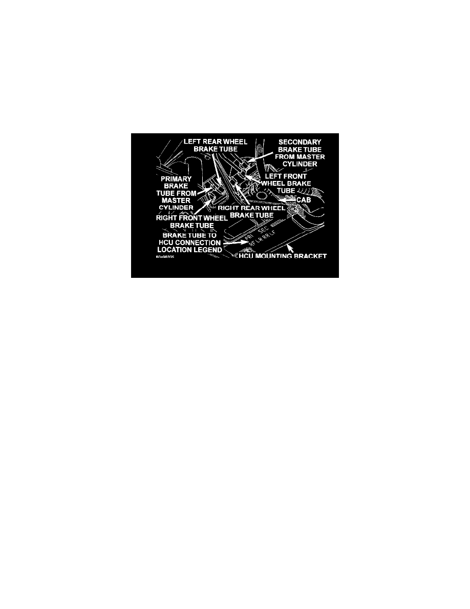
When installing the chassis brake tubes on the HCU valve block, they must be located correctly in the valve block to ensure proper ABS
operation. Refer to the image for the correct chassis brake tube locations.
NOTE: The chassis brake tube attachment locations to the HCU, are marked on the bottom of the ICU mounting bracket.
3. Install the 6 chassis brake tubes into their correct port locations on the HCU valve block as shown. Tighten the tube nuts to a torque of 17 Nm
(145 inch lbs.).
NOTE: Before installing the 25 way connector in the CAB be sure the seal is properly installed in the connector.
4. Install the 25 way connector on the CAB using the following procedure. Position the 25 way connector in the socket of the CAB and carefully
push it down as far as possible. When connector is fully seated by hand into the CAB socket, push in the connector lock. This will pull the
connector into the socket of the CAB and lock it in the installed position.
NOTE: The CAB wiring harness must be clipped to the ICU mounting bracket. This will ensure the wiring harness is properly routed and does
not contact the brake tubes or the body of the vehicle.
5. Clip the cab wiring harness to the ICU mounting bracket.