
Caravan FWD V6-3.8L VIN L (1999)
Alignment: Service and Repair
Wheel Alignment
1. Position the vehicle on an alignment rack.
2. Perform the PRE-WHEEL ALIGNMENT INSPECTION.
3. Install all required alignment equipment on the vehicle per the alignment equipment manufacturer's instructions. On this vehicle, a four-wheel
alignment is recommended.
NOTE: Prior to reading the vehicle's alignment readouts, the front and rear of vehicle should be jounced. Induce jounce (rear first, then front) by
grasping the center of the bumper and jouncing each end of vehicle an equal number of times. The bumper should always be released when vehicle is
at the bottom of the jounce cycle.
4. Read the vehicle's current front and rear alignment settings. Compare the vehicle's current alignment settings to the vehicle specifications for
camber, caster and toe-in.
5. If front camber and caster are not within specifications, proceed to CAMBER AND CASTER below. If caster and camber are within
specifications, proceed to TOE which can be found following CAMBER AND CASTER. Rear camber, caster and toe are not adjustable. If found
not to be within specifications, reinspect for damaged suspension or body components and replace as necessary.
CAMBER AND CASTER
Camber and caster settings on this vehicle are determined at the time the vehicle is designed, by the location of the vehicle's suspension components.
This is referred to as NET BUILD. The result is no required adjustment of camber and caster after the vehicle is built or when servicing the
suspension components. Thus, when performing a wheel alignment, caster and camber are not normally considered adjustable angles. Camber and
caster should be checked to ensure they meet vehicle specifications. If front camber is found not to meet alignment specifications, it can be adjusted
using an available camber adjustment bolt package. Before installing a camber adjustment bolt package on a vehicle found to be outside the
specifications, inspect the suspension components for any signs of damage or bending.
CAUTION: Do not attempt to adjust the vehicles wheel; alignment by heating, bending or by performing any other modification to the vehicle's front
suspension components or body.
If camber readings are not within specifications, use the following procedure to install the front camber adjustment bolt package and then adjust front
camber.
CAMBER ADJUSTMENT BOLT PACKAGE INSTALLATION
The camber adjustment bolt package contains 2 flange bolts, 2 cam bolts, 2 dog bone washers, and 4 nuts. This package services both sides of the
vehicle. Use the package to attach the strut clevis bracket to the steering knuckle after the strut clevis bracket has been modified. To install and adjust
the camber adjustment bolt package, follow the procedure below.
1. Raise the vehicle until its tires are not supporting the weight of the vehicle.
2. Remove the front tire and wheel assemblies.
CAUTION: When removing the steering knuckle from the strut clevis bracket, do not put a strain on the brake flex hose. Also, do not let the weight
of the steering knuckle assembly be supported by the brake flex hose when removed from the strut assembly. If necessary use a wire hanger to support
the steering knuckle assembly or if required remove the brake flex hose from the caliper assembly.
CAUTION: The knuckle to strut assembly attaching bolt shanks are serrated and must not be turned during removal. Remove the nuts while holding
the bolts stationary.
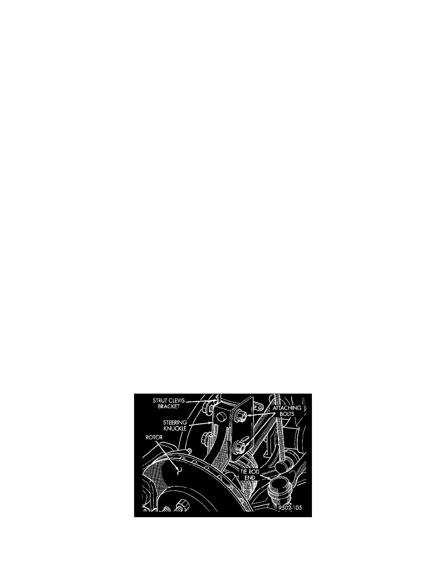
Clevis Bracket To Steering Knuckle Attaching Bolts
3. Remove the top and bottom, strut clevis bracket to steering knuckle attaching bolts and discard. Separate the steering knuckle from the strut clevis
bracket and position steering knuckle so it is out of the way of the strut.