
Challenger V6-3.5L (2009)
Sunroof / Moonroof Switch: Testing and Inspection
SWITCH - POWER SUNROOF
Any diagnosis of the power sunroof system begins with the use of a scan tool and the proper Diagnostic Procedures Information. The scan tool provides
confirmation that the Controller Area Network (CAN) data bus circuit is functional, that all of the electronic modules are sending and receiving the
proper messages on the CAN data bus, and that the sunroof switch is sending the proper hardwired output to the power sunroof motor/module assembly.
For complete circuit diagrams, refer to the appropriate wiring information. The wiring information includes wiring diagrams, proper wire and connector
repair procedures, details of wire harness routing and retention, connector pin-out information and location views for the various wire harness
connectors, splices and grounds. If completing the appropriate diagnostic information results in the sunroof switch being inoperative, perform the
following test prior to switch replacement.
1. Disconnect and isolate the battery negative cable.
2. Remove the overhead console, See: Interior Moulding / Trim/Console/Service and Repair/Overhead Console - Removal.
3. Disconnect the power sunroof switch wire harness connector.
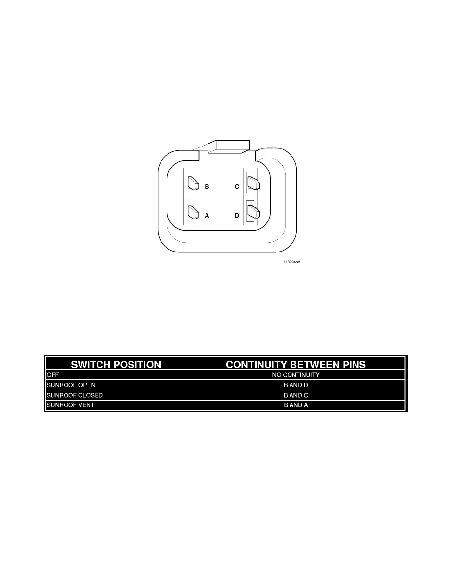
4. Using an ohmmeter, test the continuity of the power sunroof switch in each switch position. Refer to the POWER SUNROOF SWITCH
CONTINUITY TABLE. If OK, inspect the wiring harness and connectors for damage. Use a scan tool and the proper Diagnostic Procedures
Information to complete diagnosis of the power sunroof system. If not OK, replace the overhead console.
POWER SUNROOF SWITCH CONTINUITY TABLE